3D-Printing Tips: What to Do with File Formats (.PDF Download)
One can choose from a number of file formats for 3D printing, and in general they all work fine. However, understanding what mesh resolution is needed for each part can affect the size of the file, which may create lag when transferring data. In addition, not everything transfers smoothly from a CAD drawing to the printer. This article will look at file resolution, clearance between moving parts, geometric interferences, and more things to keep in mind when moving your CAD drawing to a 3D printer.
Stereolithography (STL) is the standard file type for our 3D-printing software. A mesh resolution of 0.01 to 0.03 mm and a ≤0.016-mm chord length produce an optimal STL file. To change your mesh resolution, while saving your file to STL, click on options and choose either coarse or fine resolution. Customize the .stl output with manual changes to deviation and angle to fine-tune the resolution for your part.
Note: We at Xometry prefer STEP and IGES file formats. We feel the parametric formats allow our team to be more inventive in creating support structures. However, we will work with just about any CAD format, including native SolidWorks, AutoCAD and PTC Creo (Pro/ENGINEER). Also, keep in mind that higher resolution creates larger files, and recommended settings are given for a good mix of quality and file size.
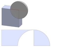
Overlapping geometry will sometimes cause problems, being misinterpreted by printer software when being converted into 2D layers. To ensure proper interpretation, multiple bodies are always unified, merged, or Booleaned together.
Keep in mind that higher resolution creates larger files, and recommended settings are given for a good mix of quality and file size.

