Getting Robots to Walk
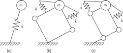
At Oregon State University, Professor Jonathan Hurst and his teams are developing walking robots based on a simple, stripped-down model of the legs on humans and other two and four-legged animals. The model, the spring-loaded inverted pendulum, consists of just a mass and spring connected by a leg component, and has been extensively studied in the biomechanical and robotic communities.
The goal is to design a robot that behaves and walks exactly like the simple, understandable model, and then write controller software and apply it directly to the that robot, says Hurst. “This contrasts with how engineers usually develop controls for robots,” Says Hurst. “First they build the hardware and identify how that hardware works as a system, then write controllers to make the system do what they want.”
This attitude is embodied in the names of their recent robots, Atrias 1 and Atrias 2. They are acronyms for “Assume The Robot Is A Sphere,” a variation on the punch line to a joke in which a mathematician simplifies a problem way too much. “We want to build a robot that walks based on a very simple stripped-down model, one that lets us easily develop controls for it,” notes Hurst
Why walking robots?
Hurst and his team are solely focused on developing the hardware that will give a walking robot a natural, humanlike gait. They are unconcerned with giving the robot sight or hearing or the ability to navigate or even carry a load. “We are addressing the low-level dynamics and behavior of locomotion,” says Hurst. “Once we have that, we can work with colleagues in the control and artificial-intelligence communities to add other capabilities.”
Hurst does want to understand how the leg’s muscles and tissues can be copied in robots, and how natural legs carry out walking and running, and subsequently develop control techniques and actuators that will recreate the natural dynamics of walking. This will let him devise robots that can travel over moderately rough ground, across slight dips and rises, and through gravel and mud with little need for inputs about the surroundings or complicated control algorithms. The robot won’t have to look for or adjust its behavior to travel across these simple obstacles. Hurst likens control of such a robot to playing a first-person-shooter video game. The player doesn’t worry about what his onscreen avatar is walking over, he just points and the avatar moves about.
“But once you want the robot to cross a creek on irregular stepping stones or climb a spiral staircase or a ladder, then the gait needs to change, and the abilities to recognize obstacles and change the gait will involve other’s engineers’ efforts in perception and intelligence.”
There are several reasons Hurst is committed to walking robots as opposed to ones that roll on wheels, fly, or use some other exotic form of locomotion. “We have designed our environments for us, two-legged beings, and if we want robots that can get around in our environment, it makes sense that they would walk. For example, when Japan needed a robot that could get into the disabled Fukushima Daiichi nuclear-power plant, they needed on that could go up stairs and ladders, over debris and through doorways. They needed one that could walk.”
Hurst believes biomedical engineers could also build better prosthetic legs based on the information he and others uncover on modeling and recreating a walking gait. “We could have artificial legs that work more like their biological counterparts,” says Hurst, “And we could have exoskeletons that work with a person rather than treating the person inside like a puppet, as many currently do.”
Another reason Hurst is committed to replicating the human gait with the simple mass-spring model is because it’s so efficient. Humans and other animal exert relatively little energy in walking or running, thanks to their tendons and tissues acting as springs to conserve energy as their muscles do the work.
The W Prize: An obstacle course for robotsTo spark interest in walking/locomoting robots, Tad McGeer, a pioneer in robotics who developed the concept of passive dynamic walking, founded the W Prize. It will award at least $200,000 to the first team or individual that can field a locomoting robot, most likely a walking robot, that finishes a 10‑km obstacle course in 10,000 sec (2.8 hr) or less and uses no more than 10 kJ of energy for every kilogram of the robot’s mass. The Prize is meant to advance the state of the art in practical applications for walking robots and get the public interested and excited about robots. The challenge takes place on a 200-m circuit that contestants must complete 50 times. Four obstacles along the course test the robots’ dexterity and stability. And the first obstacle, a size-limiting doorway, also forces robots to be somewhat human sized. Each robot must start the course by entering and holding position inside the doorway. It measures 1.7‑m tall, 0.8‑m wide, and 0.5‑m deep. After each out-and-back run though the course, robots must exit through the arch, turn around, and reenter it within 4 sec. The second obstacle consists of 20 elevated and unevenly spaced stepping stones. The “cinder-block” stones are all the same height (at least 0.39‑m tall, and 0.23 × 0.23‑m square on the top). Distance between stones varies. Robots must walk or move using only the tops of the stones for support. The robots have 25 sec to get from the first to the last stone. The “disappearing” ditch obstacle consists of three slightly elevated flat panels. On half the runs (randomly chosen) over the 10‑k course, the middle panel will be removed, leaving a wide but flat-bottomed ditch to traverse. On every fifth time through the course — once every kilometer — robots must climb a set of six stairs, turn around on a landing, then descend the stairs, all within 10 sec. Stairs are not included on every circuit so that they don’t dominate energy-consumption considerations. Robots can be remotely operated and teams have the option to place sensors along the route, as long as they don’t provide energy to the robot. Teams will also have a detailed scaled drawing that shows all the dimensions and placement of obstacles Other rules dictate that robots must use the same means of propulsion/locomotion on all parts of the course. So an entrant cannot roll for one part, hop for another, then deploy eight legs for another. No person or object can interfere or touch a robot while it’s on the course. Living tissue cannot be a functional part of a machine. And robots must touch the ground (or an obstacle) every 3 sec, so flying is out. Jonathan Hurst is confident a robot will successfully complete the W-Prize obstacle course within 5 to 10 years, but not be able to do it in the allotted energy budget. “That’s a lot farther off,” he predicts. |
He points to other walking robots, particularly those from Boston Dynamics, Waltham, Mass., such as Big Dog and Cheetah. “My friends at Boston Dynamics put hydraulic actuators on the limbs of their robots that generate all the force and dynamics they need,” says Hurst. “But every time a robot like that comes down and decelerates its mass, it wastes energy. And every time it hops or moves forward, it generates more energy that will be wasted once it lands. It’s not very efficient. But their plan is to build robots that can walk or run and carry great loads, then work on the control algorithms to make them as efficient as possible.”
Atrias 1 and 2
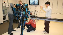
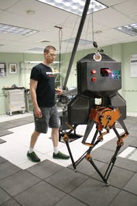
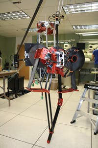
Atrias 1 is a monopod or one-legged robot and, fortunately, the mass-spring model works for one-legged locomotion. “Although we knew the ultimate robots would have two legs, we started with a monopod because it would be simpler and less expensive,” explains Hurst. “It lets us see what would and wouldn’t work, and then use those lessons on Atrias 2.
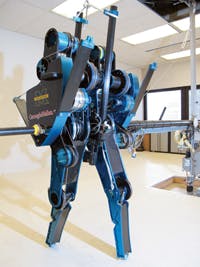
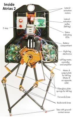
Both robots have legs made of carbon-fiber tubes with small, aluminum components making up the knee joints. The theoretical mass-spring-model on which the robots are based calls for massless limbs, an impossibility. “The legs weigh about 2.5 pounds and support the entire 132‑pound robot, so they represent about 3% of the robot’s mass,” notes Hurst. “They obviously couldn’t be massless, and their mass means that every time they hit the ground, there’s an inelastic collision that wastes energy. But we knew we couldn’t match the ideal components in the model. The mass is small enough, though, that we consider it negligible.”
Both Atrias 1 and 2 rely on fiberglass plate springs. The team ruled out air springs because they exhibit some hysteresis, and are nonlinear and not too efficient. And coil springs were not used because they don’t have enough energy density. Instead, both robots are outfitted with fiberglass springs that are relatively light for the energy they store. The goal is to store about 100 J. They also closely follow the traditional spring equation, F = kx, regardless of the direction they are flexed, and can be built with any spring rate. Hurst uses fiberglass from Gordon Composites, Montrose, Colo., a firm that sells similar materials to companies making archery bows. Fiberglass springs are also used to damp vibrations in heavy machinery and as springs in furniture.
Atrias 1 used cable drives to move its single leg. They were all pretensioned and each cable terminated on a pulley, so power never got transmitted through friction. “Cable drives are incredibly efficient and have zero backlash,” says Hurst. “That is important because we repeatedly apply positive and negative torques as the leg goes back and forth. Gearboxes, another option, all have some degree of backlash.”
Cable drives are also light compared to the torque they can transmit. Atrias 1’s drive had hundred of Newton-meters put through it, yet it didn’t weigh much, according to Hurst. The major downside is the size.
So for Atrias 2, which would have two legs and would have required two cable drives, the team switched to a harmonic drive. It is compact, but has other issues. “For example, it is inefficient and we waste energy trying to push torque and power through it,” says Hurst. “And we wanted a gear ratio of 23:1, but the smallest ratio we could use on a drive that fit our design was 50:1. This limited the design but it works.”
Atrias 2 carries four motors, two for each leg. For the leg motion, the team chose a pair of brushless, frameless dc motors. The team custom built housings and sensors for them. “These motors control leg length and swing and are the main locomotion motors,” says Hurst. “They had to be pancake motors with large diameters, minimal mass, and good torque density.”
The other two motors control abduction and adduction for lateral balance and ended up being standard motors from Kollmorgen, Radford, Va. “They aren’t as light as we’d like, but we mount them so that their mass has minimal effect, and it seemed a small price to pay in mass to avoid the expense of custom building two more motors.”
The robot uses 32‑bit Renishaw encoders on every degree of freedom to act as proprioreceptors. “They keep us informed of the position and speed of all leg components, the deflections of all the springs, speed of the motors, and orientation of the robot’s body,” says Hurst. “There are no sensors looking at the surrounding environment.”
Computing power comes courtesy of an I5, a small desktop computer running on an EtherCAT bus. Sensor and encoders are run from a microcontroller board that communicates over the EtherCAT net back to the computer. “The main PC runs a real time O/S that receives all sensor data, handles all the number crunching, and sends out commands, all at 1 kHz,” explains Hurst. “We wouldn’t be able to send that much data that quickly over a CANbus or any other alternative. We had to search far and wide to come up with this solution.”
Power for the 132‑lb robot comes from a 51.4‑V three-battery pack carrying lithium-polymer batteries usually used in model airplanes. The robot draws about 400 W when walking, so the pack let Atrias 2 walk for about 30 min.
The team is currently working with Atrias 2, seeing if it can duplicate what the models shows is possible. For example, they want to get Atrias 2 walking at 4 m/sec, which simulation shows is possible. It should also walk at slower speeds using the same springs and other hardware.
This file type includes high resolution graphics and schematics when applicable.
Resources: Dynamic Robotics Laboratory, Oregon State University
