From Napkin to Final Product, One PCB Design’s Journey (Part 3)
This file type includes high resolution graphics and schematics when applicable.
Did you miss Part 2? Check it out here.
And for Part 1, click here.
The Build
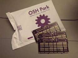
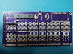
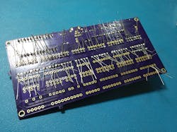
Right on time, 12 days later, I get the boards. They looked great! All my chips and pins fit perfectly. To me, a work of art. To others, an unproven PCB rectangle. But to an electrical engineer, a printed board, in hand, is a success. Having it work is ancillary—we’ll always make it work.
They came in a USPS document envelope. I picked that, since I want to support the good old Post Office. Inside was another bubble padding-infused envelope from OSH Park containing my three boards and a sticker.
The boards are clean. All copper points were well defined and accurate. The sink screen printing: also well-defined. There were a few “hanging chads” (remember those?) around the periphery of the board, remnant of being part of a larger panel. I snapped them off with ease. A tiny bit of an edge is left where any tab attached. Not an issue at all.
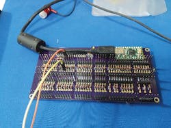
Setting up one key was the next step. Engineers expect a first-gen board to have some sort of design flaw. So, I only attached the bare minimum parts and only assembled one set of pins…for the letter “a.” After assembly, I loaded the code onto the chip. From each pin I pushed on two of those project wires, so popular with the maker crowd. I opened Notepad on my PC. I touched the two project wires together.
Then I held the wires together for a bit…
Aaaaaah…
It worked!
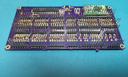
I assemble the rest of the board over the next hour. It was a lot of soldering: 398 soldering points total!
The final build looked like a bed of nails at this point (as expected, of course). I then went on to test each letter and symbol, and they all worked. It had 62 regular asci character keys, including the arrow keys. These are the keys I would have wanted easy access to back in my emulation gaming days.
(A note about soldering: Here is one of the greatest mysteries in all of electrical engineering. Why, when you are soldering, no matter what you do, does the solder smoke goes straight into your face? I try holding my breath, moving to one side, blowing out…but it always heads straight to the face. Why not use an exhaust or a fan? That’s the logical solution, but these devices just try to defeat that ancient mystery—it is no solution to the original “why.” Is it micro-gravity of the human body? Air pressure differential caused by turbulence around one’s head? Solder seeking to hurt us? Who knows…)Afterthoughts, Issues, and What’s Next
The KB Breakout brings more than 100 inputs to a system. However, how quickly could any one input be read depends on the polling rate of a keyboard on the platform. Take a PC: The typical maximum polling rate for a keyboard is 1,000 Hz through USB. This would mean your input triggers would have to come in slower than 1ms (1/1,000), making the KB Breakout useful for many different applications, but not all.
I will address the refresh rate with a higher than standard frequency would make it more useful for test rigs. However, there must be a maximum switch close vs input detection frequency. Although it's beyond human ability to press a button faster than a few times a second, I suspect this will be hooked up to external machines.
I realize now that some asci characters are accessed on a keyboard while holding down the shift key. V2 will have those keys built in, but in the code be a combination of both shift and the corresponding key. That will give the user 18 more keys to work with. Addressing the F# keys will also be a priority. Since I still play a lot of first-person shooter (FPS) PC games, I would love to make a stompable series of buttons for the F# keys, since the gamepad I use (Nostromo n52) has no F# key access. Gaming aside, I really want access to every single standard keyboard input.
Speaking of the Nostromo n52, this gaming keypad (named after the ship in the movie “Alien”) is near-perfect. No new version that followed it captured that perfection. There was always something wrong: keys not tall enough, too flat, removal of the thumb d-pad for a joystick, etc. My plan is to recreate all the best parts of the original and add some of my improvement ideas, using the KB Breakout and a 3D printer.
I plan to write all-new code to add more keys, as I said, but to also make input from the keys faster and closer to what an arcade input would experience. That may or may not translate into an improvement for FPS and strategy games. I would offer the ability to switch between regular keyboard mode, arcade mode, and PC gaming mode. Oh boy, a DIP switch on the KB Breakout? That is a very old-school approach to selecting states. A single selector button and a multicolor LED would be best.
I’ll make sure compatibility is sound across every platform I can try, fom MACs to Udoo SBCs.
Lastly, I’ll start prepping to open-source the whole design (eventually).
All in all, this journey was refreshing. To see an idea come to life and become usable with the first prototype is tops, in my book. In a small way, I hope the story of my journey will inspire others to follow their whims and dreams.
For me, the trip isn’t over. The biggest step remains: taking it to the market. Wish me luck.
Before and during Crowdfunding
This will be my first foray into the crowd-funding world. It’s intimidating, to be honest. There are so many places to launch, now. Should it be Kickstarter, Indiegogo, Rocketdog, or some other place? What do I need? Where do I begin?
Here is my novice checklist:
- At least a prototype board finished, for proof of concept (check).
- Video of the board in use, various uses (partially checked).
- Ambient soundtrack for the background of the videos, like any crowdfunding campaign has now.
- The actual price for a board and parts, as a kit or assembled, which will also dictate the funding goal.
- Perhaps make those 2wycked shirts I mentioned previously.
- Pick which site to launch on.
- Promote like crazy!
I must stop here. I hope my crowdfunding campaign will be a happy conclusion for this development story. Stay tuned. And…if you want one of the prototype boards, contact me. I think I could spare one or two.
This file type includes high resolution graphics and schematics when applicable.
About the Author
Cabe Atwell
Engineer, Machinist, Maker, Writer. A graduate Electrical Engineer actively plying his expertise in the industry and at his company, Gunhead. When not designing/building, he creates a steady torrent of projects and content in the media world. Many of his projects and articles are online at element14 & SolidSmack, industry-focused work at EETimes & EDN, and offbeat articles at Make Magazine. Currently, you can find him hosting webinars and contributing to Penton’s Electronic Design and Machine Design.
