Closing the Manufacturing Loop (Part 4): Inspection
At a Glance:
- The final installment in a four-part series article focuses on the inspection phase when using CAD/CAM tools to design a golf putter.
- CAD/CAM software used for CNC programming and simulation could also be used for designing, creating and inspecting the golf putter.
- The author highlights how closed-loop manufacturing offers flexibility in the overall design and production of the component.
At this point in the closed-loop manufacturing process, the part is almost complete. First, the 3D model was created via a handheld probe connected to CAD software. Then, the model was converted to a file type that was accepted by the 3D printer. The part was printed, sintered and sent on to subtractive machining. NC code was created within a CAD/CAM program, simulated and verified. Finally, the part was machined. This last installment in the series covers the final stage in the closed-loop manufacturing process: inspection.
Production thus far has already incorporated in-process inspection. Rather than relying on traditional indicating, which requires operators to physically stick their heads and hands inside the machining unit to check the process with dial indicators and edge finders, CAD CAM Consulting Services (CCCS) chose a safer route.
READ MORE: NASA Envisions Design Differently
Offsets and origins were automatically—and much more safely—measured with probing software, rather than people. Probing eliminated any unnecessary risk to limbs and meant that the part would not need to be taken out of the machine and re-fixtured in the event of a tricky geometry. The operator simply needed to close the door and start the machine.
Writing Code for CMM Inspection
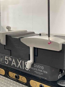
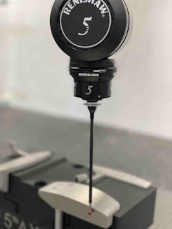
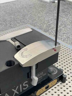
The very last piece of the programming process was to write code for the coordinate measuring machine (CMM) inspection using CCCS’s usual CAM and inspection software. CMM units are sophisticated metrology devices that use probes to measure part geometries in different dimensions. Some CMMs, including CCCS’s, have 5-axis capabilities. They excel in tracking deviations from one surface to another, like when a critical plane must be perpendicular to another to achieve the best bore.
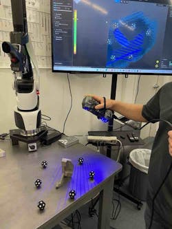
Similar to the handheld probe mentioned in the second article in this series, a CMM creates a point cloud of the part’s surface area. This data is compared to the part’s design intent and original model. The average CMM can relate geometries to within one micron. The program directs the CMM in the best way to take these measurements.
READ MORE: Outsourcing CAD Engineering Delivers Savings, Flexibility
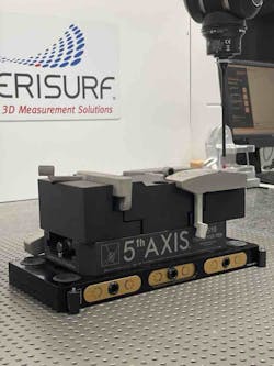
Once the part is machined, and the operator is confident that the part is good, it goes to inspection. CCCS’s CMM is situated within a modular work system, meaning the part had to travel minimal distance from where it was machined to where it was inspected. The CNC machine even held the same plate for mounting the fixture as did the CMM. To conserve time and material, the same soft jaws used to hold the casting were used during CMM inspection. Creating a new workholding device would have tied up a 3D printer, a CNC unit and required extra material.
Creating a Single Perfect Fixture
It is common practice to use two different but adequate workholding tools for machining and inspection, but the CCCS team knew the advantage of creating a single perfect fixture. The different units often must reach different sections of the part in different ways. If the fixturing gets in the way of machining or measuring a critical point, it is useless. When building the fixture, the programmer was mindful of how the fixture was going to behave in both machines. Fortunately, the CAD/CAM software used for CNC programming and simulation could also be used for designing and creating the fixture.
The same simulation and verification software that was used for the part itself was once again used during the CMM inspection process. That software allows users to simulate, in real-time, the actions of the CMM using a digital twin. Simulation follows the entire measurement workflow from start to finish. This way, the inspection probe is sure to take the safest, most efficient path.
Once again, the software is saving the operators from having to use “dry cycles,” wherein they run the program as a test, possibly sacrificing probes and wasting machine time. Instead, the code itself is analyzed thoroughly for syntax errors or potential collisions. Best of all, the software does this almost instantaneously, eliminating the need for programmers to tediously proofread each line of code. After the code is checked, inspection can take place.
Combining Additive and Subtractive Manufacturing
The inspection process requires not only that each key element is measured, but also that there is proof of it. CCCS’s chosen software automatically creates complete documentation of every critical metric and comparisons against the design plan. With a simple series of clicks, users can print or send off a color-coded inspection report, complete with tolerances and time stamps.
READ MORE: Beyond Traditional Machining: Hitting All the Right Notes in Custom Manufacturing
At the end of inspection, manufacturers have a well-made part and its associated data, collated to make process tracking simple. The report will include how the part was made as well as metrics on how it holds to tolerances. In the case of the golf putter, the production team was pleasantly surprised at the end of manufacturing.
Some members had been skeptical of 3D printing a part with a carbon fiber polymer; historically, accurate and resilient parts have mostly been machined. Once the CCCS team members witnessed how additive and subtractive manufacturing worked together, though, they were convinced. This combined approach reduced weight and vibration and gave the team more flexibility.
Throughout the process, CCCS employed software tools that worked seamlessly with each other. Moreover, this approach allowed the manufacturer to use only one computer. From reverse engineering to final inspection, the part file stayed cohesive and coherent. This is a founding principle of closed-loop manufacturing, where all the manufacturing processes are connected. It comes down to communication.
Synchronize to Optimize Closed-Loop Manufacturing
Rather than relying on KPIs and analyses from general statistics, shops that use closed-loop manufacturing are incorporating the absolute best, most applicable data to inform their processes: their own. Connecting every step of manufacturing provides shops with near constant feedback on efficiency. It keeps processes trackable and controllable.
Closed-loop manufacturing also offers shops flexibility regarding manpower. Because the process is so connected, one person at one console could direct the entire manufacturing of a part. However, the closed loop also means that production can be offloaded at any point with no loss of data. The file can move between departments, or even among subcontractors or clients, without disrupting a micron. That file is essentially a blueprint of the entire production process.
This level of connectivity is often daunting. Many veteran manufacturers are hesitant about leaving so much in the hands—or lack thereof—of software. But the results speak for themselves. Closed-loop manufacturing slashes time spent designing, prototyping and coding. It funnels manpower to where it is most needed. It eliminates wasted material. And best of all, it informs shop decisions with the most relevant data possible.
The team at CCCS took on the golf putter project to highlight the many benefits of closed-loop manufacturing. By choosing a part that was difficult to hold and machine, CCCS demonstrated that this efficient and safe approach to design and production would benefit any industry.
