Closing the Manufacturing Loop (Part 2): Reverse Engineering and Additive Manufacturing
At a Glance:
- The author explains how an infrared laser scanner can be used to scan a golf putter before it is reverse engineered for an additive prototype.
- The shop’s reverse-engineering software began building a 3D model of the part even before the scanning process was completed.
- Consideration is given to the compatibility of specified software and associated additive methods across systems over legacy manufacturing technologies.
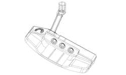
As providers and trainers of some of the most powerful manufacturing software available, the team at CAD/CAM Consulting Services, Inc. (CCCS) needs to know exactly what is possible in manufacturing. Rather than tackling problems as they come, the company instead creates its own challenges. Recently, CCCS put its collection of modeling, simulating and manufacturing software to the test by creating a golf putter. The first stage of production was reverse engineering and additive manufacturing of the part.
READ MORE: Replacement Parts are a 3D Print Away
Scanning the Putter Using a Handheld Device
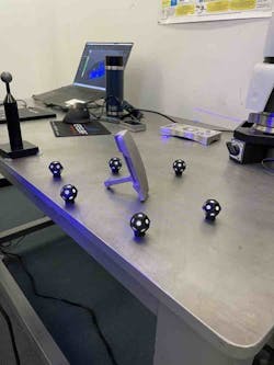
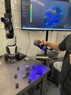
One of the most challenging tasks that may come up is transferring an odd-shaped part to the computer. Fortunately, specially designed hand scanners built precisely for this purpose are becoming much more accessible. The scanner used for the putter is an infrared laser about the size of an old telephone receiver. As it passes over the part, it bounces back the depth of each point on the surface, laying down millions of points to create a digital representation of the part. The way it measures and reports the topology of the part is essentially the same technology used to scan the bottom of the ocean floor to get its topography.
In this application, it was easy to scan the putter, but the handheld device is able to scan objects up to the size of a rocket. It can even scan around mating areas, where the part is going to connect with another plane or component. This is crucial when brackets and other connections are required for an assembly. Those mating parts around that assembly can even be used as fixturing to hold the part. What better way to design a work-holding tool during machining than to use the connection between mated parts?
Use Reverse-Engineering Software to Build and Validate a 3D Model
As the putter was scanned, those millions of points showed up in the system automatically. The shop’s reverse-engineering software began building a 3D model of the part before the scanner was even set down. It took the digital point cloud provided by the scanner and overlaid the correct surfaces. The software includes a specific feature that inspects the model in real-time as it’s being built. Those surfaces were then converted into a solid model that was pulled into the local CAM system. This primary model is kept as a type specimen; it’s the model that will set the foundation and be considered “law” for future inspections.
The software allows users to add model-based definition (MBD) to the 3D model, which is a huge advantage in communications. Model-based definition allows digital documentation of notes and dimensions. It improves accuracy and efficiency and allows for ease of CMM programming inside the inspection software without the need for a paper trail.
Many tier-1 parts are not typically produced by the parent company itself. They’re made by supporting shops. The part may go to three or four of these shops before returning, and the files need to follow. Not only must they follow, but the files must also be detailed, translatable and verifiably correct at each point.
READ MORE: How CAD for CAM Solutions are Addressing the Top Five Manufacturing Workflow Challenges
Using software that can interact with different CAD and CAM systems without losing any data or comprehension is critical. It is even recommended to use additional validation software that checks the model after it is translated from one system to another. The validation software used by CCCS, for instance, analyzes the models and compares every data point to ensure a flawless transition. In an aerospace environment, for example, the software is Boeing B6 quality-assurance-standard approved; Boeing shops use it to check each digital model after translation. Current ITAR and AS9100 requirements demand traceability across a part’s entire manufacturing history. Software that performs tracking is vital to all industries.
This compatibility across systems makes it possible for manufacturers to establish themselves as prototypers or designers, too. Users can design their parts and test them in their shop before sending them almost instantaneously to where they will ultimately be made. No concern for shipping costs, material handling and machine use.
Benefits of Selecting Additive Manufacturing
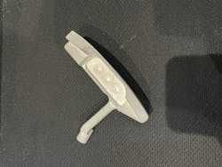
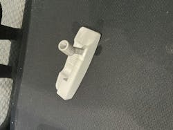
The next step in the process was to use the CAD model to reverse engineer the part. The CCCS team used a metal 3D printer similar in style to a unit a hobbyist may use, although there are options for production use in larger shops. Additive manufacturing was chosen over subtractive manufacturing—traditional machining—because printing the part would take much less time as opposed to traditional subtractive manufacturing.
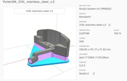
The system is office friendly in that it can sit within a cubicle in the engineering department. It’s a standard FDM-style printer with a nozzle that extrudes a metal-polymer mix. Just like any 3D printer, it takes a CAD file and uses it to direct its extrusion. This is where the 3D printing software comes into play.
Because of the stresses and dynamics of the printing and finishing process, the software must calculate every motion exactly. First, it scales the part up around 25% to account for shrinkage later. Then it anticipates physical stress during printing and heat treating. Imagine printing a very long, thin part. Most likely, it will bow in the middle due to gravity. The software accounts for that bowing and directs the unit to print an opposite bow. After sintering, the part will be completely straight.
The Bonding Phase
After the part is printed, it is considered to be in a green state, which means it is extremely soft. That’s when it goes to the sintering furnace to be heat treated. Here, the oven—about the size of a chest freezer—brings the part up to a predetermined temperature based on its composition. The metal-polymer mix must be brought to just before its plastic’s melting point, held there for a time and then heated even more to melt the polymer.
The polymer, which was crucial during printing but no longer needed now, melts away, leaving the metal to fill its space. The temperature is raised again, following specific instructions from the software, to anneal the metal together well. When the part exits the furnace, it is essentially the same as a cast part. Cast parts do not offer nearly as much flexibility, though. If a user prints something and doesn’t love it, they can simply tweak the design and reprint. If a casting company didn’t like their part, however, they’d have to go back all the way to remaking the molds.
Consider Surface Thickness
In the case of the putter, it was printed with too thin a surface thickness the first time around. When it came to printing and sintering the putter head, the programmers played around within the 3D printing software to find the best surface thickness. Printing gives users a huge advantage in regard to weight; it’s simple and easy to add a honeycomb structure to a part interior to reduce weight and material costs.
READ MORE: Finding an Additive Manufacturing Solution
That outer shell, however, often needs to be a certain thickness to allow machining actions on its surfaces. The putter needed to have material machined off its face, for example. The 3D printing software made it easy to experiment with the surface thickness to maximize sturdiness while minimizing material.
Cost Advantages Cannot be Overlooked
The software also lends support on the estimating side of things. It calculates cycle time between the printer and sinter, but it also calculates cost based on material prices. Users can present the customer with the total cost, down to the last cent, before production begins.
Who is Flocking to 3D Printing Software?
Before CCCS took on this specific 3D printing software, it looked around at other companies that were using it. It was astounding. Famous jewelry brands are using the software to print beautiful forms in silver and gold. Medical companies are using it to fabricate incredible life-saving parts. Some aerospace manufacturers are producing up to 90% of their parts with it.
Finding Balance
Additive manufacturing has been around for 30 years but has recently become more economical and precise, which can only benefit traditional manufacturing. The need for subtractive machining will always exist, but pairing the two manufacturing strategies allows companies to produce parts they might never have dreamed of before the advent of additive. There’s a promising marriage between the two technologies. They enhance and balance each other.
At the end of the reverse engineering and additive manufacturing portions of producing this putter, CCCS had successfully made a part very similar to a casting. The next stage required precision machining directed by powerful CAM software.
Also in This Series
About the Author

Robert Dusenbury
Technical Applications Director, CAD/CAM Consulting Services, Inc. (CCCS)
Robert Dusenbury is the technical applications director at CAD/CAM Consulting Services Inc. (CCCS), Southern California.
