Closing the Manufacturing Loop (Part 3): CAD/CAM, Design for Manufacturing and Simulation
At a Glance:
- This third installment in the golf putter design series moves the process from reverse engineering and additive manufacturing to CAD/CAM software.
- Turning attention to the role of CAD/CAM software in the design and manufacturability of the putter, the author describes how backplot, verify and machine simulation was used to double check the machining program.
- The simulation software is used to verify the G-code and ensure that the machine will run as specified and benefit from a digital twin of a CNC machine.
A golf putter is a complex part and was chosen because it is hard to hold, hard to machine and hard to inspect. It’s the perfect part to showcase closed-loop manufacturing and the advanced technology used in this project.
In this installment in an end-to-end guide to the design and manufacturability of a golf putter, CAD/CAM software takes center stage. CAD/CAM add-ons—namely simulation—and design for manufacturing (DFM) form the backbone of the golf putter project and highlight CAD CAM Consulting Services’ expertise in closed-loop manufacturing.
The principles of DFM drive decision-making throughout the product development cycle. Simplifying part design to make a better part at a lower cost was the goal. Adhering to DFM principles resulted in increased product quality, smoother assembly, improved sustainability due to decreased scrap and waste, and streamlined production processes.
Closed-Loop Manufacturing Fits Any Size
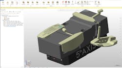
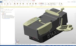
To demonstrate how closed-loop manufacturing can be used by any company, regardless of size, CCCS used one computer and one part file to create and control the entire manufacturing loop from inside CAD/CAM software. The putter was designed using the CAD tools available in CAD/CAM. The tools were used to enhance a solid model, which was needed to create the soft jaws that held the part. Model preparation tools prepared the part for machining in conjunction with the soft jaw design, all within CAD/CAM. The model for the jaws was saved as a stereolithography (STL) file and sent to a 3D printer, which created the carbon polymer product.
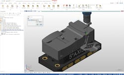
While the jaws were being processed, the part casting was still accessible. Using probing software, the technicians were able to locate parts on the machine and a program to find the work offset was written. Everything related to probing was programmed within CAD/CAM, as were several machining toolpaths. Critical features of the casting, in this case holes, were machined using contour, drilling and boring routines.
READ MORE: Making the Jump to Multiaxis Machining
In addition to probing the part to determine its location and toolpathing it, probes were used to inspect the part on the machine. Sometimes in-process inspection can be as simple as an operator stopping the machine, opening up the door and using a scale to measure and ensure a part is within tolerance.
But most of the time, additional measuring tools—such as handheld gages and calipers—are required to check diameters, wall thicknesses and more. This common measurement practice requires several human and machine interactions in an unsafe environment because the operator must stop the machine and reach inside of it to measure a part. Every operator knows the headaches caused by this maneuver.
Safety Parameters, Backplot and Toolpath
The part needed to be checked and measured, of course, but safety had to come first. The solution? In-process inspection was programmed with the CAD/CAM software. By probing the part on the machine, the measurement was taken by the probe and the work offset was automatically updated. When the CNC machine came back to cut again, it was right on size.
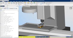
The CAD/CAM software offered backplot, verify and machine simulation to double check the machining program. Backplot made sure that the tool was cutting where it should, checked for gouges and machine simulation checked for machine kinematics, or how the machine moved. These steps ensured that the CAM program was on spec before it was converted to G-code.
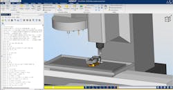
Next, the code was launched in an add-on CNC machine simulation software program through CAD/CAM. With one click of a button, all part and toolpathing information was transferred into the simulation software to run the simulation program, which is the actual G-code and a digital twin of the CNC machine out on the floor. There was no need to manually prove-out NC code. This eliminated the typical dry-run routine.
READ MORE: Design Engineering: View CAD from a Different Angle
The beauty of simulation is that it demonstrates exactly what will happen when a program is loaded into a CNC machine. It detects potential collisions, inefficiencies and errors. Any discrepancy can be fixed before cuts are ever made. If an operator likes what is shown on the digital screen and does not see any programming errors, then the code is ready to be uploaded to the machine. The operator can feel 100% confident in what was programmed in CAD/CAM and run through simulation.
Digital Twins Add Assurance
A key step in this process was making sure that all the parameters that were inside the machine control also existed within the simulation software. Once the kinematics of the machine were built from the models, parameter files were uploaded to the simulation software, so the operator was 100% sure that the machine represented on their computer was no different than the machine that was out on the floor.
The operator referred to the machine’s digital twin while programming the CAM software. The software can program within the limits of the machine, but when the program was later run through simulation, the operator was certain that the code was exactly what that machine required. Having the machine’s digital twin with the exact parameters, probing routines, G-codes and M-codes for that machine was a huge advantage.
Deburr and Machine the Putter
Once in-process inspection and simulation were complete, it was time to machine the putter. Because the part material came from a casting, it had an odd shape that had to be scanned with a hand-held device. After the scan was uploaded to CAD/CAM, facing, drilling, circle mill, contour and 3D engrave toolpaths were selected to machine part features.
The final toolpath, deburring, removed all of the sharp edges from the part. Injuries are likely to occur while deburring a part because operators are handling metal that has sharp edges and scraping away those edges with deburring knives or files. Simply removing a part with sharp burrs from a machine is dangerous. The deburr toolpath machined away all edges that contained heavy burrs, preventing potential injuries.
Simulation Software Advantages
A major benefit of simulation software is that it verifies the actual G-code that the machine will run and creates a digital twin of a CNC machine. The software will contain many of these models in its library, but not always. In that case, the machine manufacturer can provide the solid models used to build that machine.
READ MORE: Harley-Davidson Turns to Digital Manufacturing in Accelerated Timeline
The importance of simulation software cannot be overstated. Just ask anyone who has crashed a CNC machine. The CCCS team has talked to folks who have crashed spindles into parts and caused thousands of dollars’ worth of damage. Even if the machine is repaired, it may never be the same again. Simulation software prevents costly machine damage and downtime. But even more important, it ensures safety.
The biggest concern for any manufacturer is the well-being of its employees. One colleague put it best when he said, “You can be the perfect machinist for 30 years, but it takes just a split second to lose a hand or an eye.” He’s right. Safety must always be a guiding factor in design for manufacturing and closed-loop manufacturing.
Once the CCCS simulation ran smoothly and the golf putter was machined, the part moved on to inspection.
The fourth and final article in this series, “Inspection,” focuses on this last step in the closed-loop manufacturing process.
