Closing the Manufacturing Loop (Part 1): How to Design a Golf Putter
At a Glance:
- In the first of a four-part series, Robert Dusenbury provides an overview of how his team went about designing and producing a golf putter to demonstrate the feasibility and benefits of closed-loop manufacturing. He stresses that many industries—including aerospace and defense, heavy industry and transportation—that utilize castings to create parts can benefit from the use case.
- The second installment in the series focuses on the reverse engineering and additive manufacturing techniques used in this example.
- The third article focuses on using CAD/CAM software to design for manufacturing. Simulation is also examined.
- The final installment examines inspection of the putter and highlights safety considerations.
When contemplating the design and manufacturability of a new part, designers and programmers may want to consider closed-loop manufacturing. The process moves a part through the entire manufacturing cycle and minimizes waste, enhances overall efficiency and has the ability to self-correct.
Recently, CAD/CAM Consulting Services, Inc. (CCCS) designed and produced a golf putter to demonstrate the feasibility and benefits of closed-loop manufacturing. The objective was to streamline the design and production of a complex part, making it easier and less expensive to mass produce.
Although the part file that is the focal point of this article series is a golf putter and consumer product, the concept of this series extends far beyond consumer goods. Any industry—from aerospace & defense, energy and heavy industry to transportation and education—that utilizes castings in its manufacturing process to create parts can benefit from these concepts.
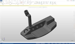
The first step in the closed-loop process was identifying the necessary components to tie into CAD/CAM software, which was the heart of this project. The ultimate goal: to research and develop, design, program, simulate, verify and inspect a part before it ever touched a machine.
The golf putter was produced from a 316 stainless steel casting using a combination of traditional and non-traditional manufacturing methods. Each of the following three articles in this series will focus on the specific technologies used to create the component while focusing on design and manufacturability.
The following is an overview of what’s to come.
Reverse Engineering and Additive Manufacturing
The second article in this series explores reverse engineering and additive manufacturing. Before the soft jaws could be designed and printed, the theoretical shape of the part casting was required. Castings are hard to hold, machine and inspect, so recognizing these factors was key to understanding and improving the manufacturability of the putter.
Determining how to hold the part influenced the choice of casting. A typical setup would include machining soft jaws—jaws that have a particular contour that securely holds or encompasses parts—versus trying to put an odd-shaped casting into a square vice. But machining the jaws came with constraints and would require a significant amount of valuable machine time.
So, instead of going straight to making a mold for the casting, the part was created on a 3D printer using 316 stainless steel. This allowed for proofing out the casting, the fixturing, the machining and the inspection process before the added cost and time of doing the casting first. By the time the castings did hit the floor, closed-loop manufacturing had been completed.
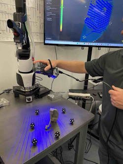
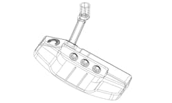
After the casting was printed, it was reverse-engineered with model-based inspection and measurement software, which included tools to scan the casting to create a solid model. Next, an exact replica of the casting was produced. The model used for reverse engineering was then uploaded to the CAD/CAM system to help create the soft jaws. 3D printing software and a printer capable of printing carbon PEEK were used.
Carbon PEEK is nearly twice as strong as aluminum and, because it is lightweight, design restrictions were not an issue. Even better? Using additive manufacturing to create the jaws took considerably less time than traditional subtractive manufacturing practices.
CAD/CAM, Design for Manufacturing and Simulation
The third article will dive into the nucleus of the project: CAD/CAM software. Design for manufacturing and simulation will be examined as well. Every step of the closed-loop manufacturing process was programmed within CAD/CAM software, including programing the fixture from the solid part. The only time the designer left the CAD/CAM software was to hit “go” on the 3D printer. Other than that, everything was tied into CAD/CAM.
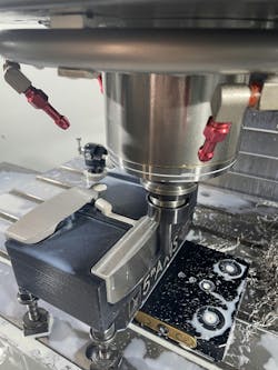
Once the 3D-printed model was created, the part location was written using probing software, which automatically generated G-code and inserted it into the NC program. For the machining program, simple mill operations programmed with CAD/CAM cut the part and a contour toolpath created a smooth finish.
While the casting was being machined, in-process inspection probes updated toolpaths as needed and the part was verified within CAD/CAM. In addition, verification software was used to create an exact digital twin of the CNC machine. The operator no longer had to run a dry cycle to make sure that the tool wouldn’t collide with the part.
A major advantage of CAD/CAM is that the user can define all needed tools and provide speeds and feeds, which can then be sent to the verification software to make sure that the program can handle them. When choosing a CAD/CAM system, invest in one with reliable partners that specialize in products that complement the software.
If the heart of this project was CAD/CAM, then design for manufacturing (DFM) was the brain. The principles of DFM—simplifying part design to make a better part at lower cost—informed all decision-making throughout the process.
Inspection
The fourth and final article of the series will examine inspection of the putter. This phase of the closed-loop manufacturing process is where safety really came into play. When CNC machines are running, it only takes a second or two for a serious accident to occur, so in-process inspection is critical on the shop floor.
Because castings are odd-shaped and inconsistent, an operator would usually have to manually indicate in each casting, which means opening the CNC machine doors and using dial indicators and edge finders while the machine is in motion. Typically, to perform this type of inspection, an operator would place one hand on the control and his head and other hand inside the machine to look around and make sure that indicating is working and within a desirable location.
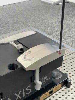
To prevent this entire scenario from occurring on the putter project, probing software was used to integrate the part location into the CAD/CAM program. Part features were probed to determine work offsets and origins. No longer was the inspection phase a possible accident waiting to happen. The first official operation in the CNC process occurred when the operator closed the door, hit the start button and the in-machine probe probed and located the casting.
After back plotting, simulating and verifying the part, CAM toolpaths were selected. The casting was easily moved and manipulated thanks to the design of the 3D-printed soft jaws. The jaws were built with multiple stations and could be moved between four separate locations for machining specific features. Each feature was located by a probe mounted on the mill.
Because the castings are often oddly shaped, an operator may have to remove a part from the machine during a cutting operation to measure it and then, hopefully, place it back in the right spot. Closed-loop manufacturing addressed this potential problem. Performing in-process inspection on the machine eliminated safety issues and possibility of human error.
The last step of the closed-loop process was to inspect the finished part on a coordinate measuring machine (CMM). This step relied on inspection software, which was programmed within the CAD/CAM program. To conserve machine time, the same soft jaws used to hold the casting during machining were used to hold it during the CMM inspection. By not having to create additional fixturing for the CMM, significant amounts of time and money were saved.
With closed-loop manufacturing, processes are safer and communication is significantly better than that of traditional production processes. If a different operator has to set up this same job at a later time, all information is documented and the process should run smoothly. For good measure, the operator can do a dry run inside of the verification software and make sure the correct tools are selected.
The main ideas behind this project were to eliminate extra steps, introduce safety as much as possible and keep the costs down. In this case, closed-loop manufacturing saved a significant amount of money because the putter took only 1 min. and 42 sec. to cut. If traditional methods were used, it would have taken days to design the fixturing to hold the part in the mill and even more time to design additional fixturing to hold the part in the CMM. By using additive manufacturing to create the casting and soft jaws, material removal was not a factor, which meant less material waste.
When the manufacturing loop was finished, or closed, all documentation for the putter was contained in one file, an efficient storage method that can prevent communication errors. This project clearly demonstrated that digital documentation is a real game-changer.
Now that the overview of the closed-loop manufacturing project is complete, it’s time to get into specifics. The next three articles in this series will break down and detail the steps, software and hardware used to create the golf putter.
Also in This Series
About the Author

Robert Dusenbury
Technical Applications Director, CAD/CAM Consulting Services, Inc. (CCCS)
Robert Dusenbury is the technical applications director at CAD/CAM Consulting Services Inc. (CCCS), Southern California.
