What’s the Difference Between Poppet and Piston Spool Valves?
This file type includes high resolution graphics and schematics when applicable.
Deciding which valve to use for a hydraulic or pneumatic system depends on a couple of design factors: the internal design of your circuit and the overall function of your valves. The two major valves used most commonly are the poppet and piston spool varieties. These valves are primarily involved with controlling compressed air.
“The main difference between a spool and a poppet valve is the construction,” explains Daniella Gonzalez-Olgren, a valve product specialist from Festo. “Because of the way a poppet valve is constructed, there is no need for lubrication, simplifying your air preparation units. However, spool valves usually have higher flows than poppet valves within the same footprint. This is because a poppet valve needs a large poppet area to create a large enough shifting force to overcome the pressure.”
Both valves have their advantages and disadvantages, but the biggest factor will be understanding your operating conditions.
The Poppet Valve
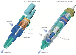
Poppet valves have a simple construction and can be used with any material. The valve functions as fluid at the inlet port passes through the control office and reaches the backside of the poppet. The tip of the spring-loaded armature closes the outflow orifice to keep the fluid trapped behind the poppet. The valve is a check valve that stops the flow, in the normal condition, from inlet to outlet. The flow in the opposite direction, outlet to inlet, occurs at a reduced rate.
The solenoid coil is energized to create a magnetic field that raises the armature to open the outflow orifice. This orifice is larger than the control orifice, which creates greater flow and a pressure drop behind the poppet. The inlet pressure on the poppet’s annulus area outside the seat diameter ousts it to let fluid flow to the poppet’s outlet.
When the solenoid coil is de-energized, the spring force reseats the armature tip—once again trapping the fluid behind the poppet and allowing it to close. Poppet valves are typically preferred in sorting applications, industrial environments with possible contamination, and any applications that need fast switching times.
Advantages
Unlike spool valves, poppet valves open an immediate flow path to the outlet. This results in a fast response time. Poppet valves only open as much as is needed by the flow going through it, traveling a minimum distance to do so, which increases its response time. The large surface area that is essential for poppets results in a higher flow rate. Poppet valves require small actuation strokes, which allows for shorter switching times.
The fact that poppets can be used with any material also makes them very inexpensive and easy to use. Other benefits of poppet valves are that the axial sealing used is resistant to soiling, and they do not require lubrication. This makes them chemically compatible with lubricated compressed air. Poppets are also beneficial when it comes to longevity, as less wear on the internal seals leads to a longer product life.
Disadvantages
Due to the constructional constraints, poppet valves are not advantageous when it comes to the relationship between space and flow. The disadvantage of poppet valves is that, as the poppets shift from one flow path to another, air is free to travel in any direction. This is known as “crossover.” With pressure-independent models, poppet valves offer a lower flow than slide valves.
This is due to the greater structural demand—in pressure-dependent valves, the control pressure depends on the operating pressure. The valves are unbalanced and pressure must be supplied under the poppet to hold the valve in the unactuated position. To allow air flow, a higher force is required to actuate the valves since it has to overcome the spring and the air pressure. It is also possible for the valve to open due to back pressure if the supply pressure is removed. This makes them poor choices for holding pressure downstream.
Poppet valves also typically operate in one manner. For example, a two-way, normally closed poppet valve cannot be changed to open. Poppets are typically not recommended for vacuum conditions. Lastly, the valve construction is not always without overlap. Depending on the design of the poppet valve, the switching of positions can lead to overflowing between channels. This may cause unnecessary leakage and noise.
Piston Spool Valves
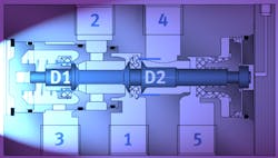
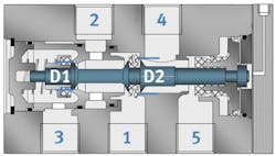
A spool valve features seals along its surface. By actuating the valve, the spool shifts, causing the seals to travel down the bore and opening the ports to allow for airflow. For systems that have a flow of 100 gpm or less, spool valves are most commonly used to direct flow. By counting the number of ports that fluid can travel in any given valve provides you with its number of ways.
For example, a two-ported valve is also a two-way valve. The two-way valve will only have two positions, since it can only stop or allow flow. Other spool-valve configurations are three-way, four-way, and five-way. Five-way valves are special cases in the fact that an exhaust port is not a concern.
A four-way valve may have five ports with its tank ports connected internally in order to eliminate an extra port in the body. This configuration is important for hydraulic purposes because it helps reduce leak points and piping. Spool valves are typically preferred in lightweight machines or end-of-arm robot tooling; clean work environments; and especially cabinet installations or whenever there are space constraints.
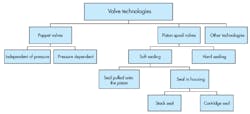
Spool values can adopt one of two types of sealing systems: hard or soft sealing. Hard-sealing systems are more durable. The absence of the soft rubber sealing elements in the piston spool valve is what makes them more durable. A valve using this type of seal is immediately ready for a full dynamic use, regardless of whether it has been inactive for a long period. However, this makes hard seals more demanding.
The challenge is that the air gap surrounding the moving piston cannot be larger than a few micrometers. The often-used metal sleeve acts as both a seal and a guide for the valve spool. The sleeve and the spool must be made of the same material, since a difference in thermal expansion coefficients can cause greater leakage and even jamming of the spool.
Even a small deformation in the housing can damage the sleeve and affect the life valve and increase leakage. While being robust and durable, hard-sealed spool valves will always have a certain amount of leakage due to the air gap, and their flow capacity is lower when compared to other valves of similar dimensions.
Soft-sealed spool valves use rubber gaskets (O-rings or molded elastomer seals) on the piston. By using soft-sealed spool valves, you avoid the complications of having metal-on-metal configurations. However, soft-sealed spool valves will wear down quickly over time when in contact with the channel edge or control edge. Optimal planning for the control edge is necessary, and careful consideration must be given to the molded elastomer seal and piston guide, to ensure a soft passage with minimum degree of wear.
The seals can be mounted directly onto the valve housing. Again, the required recesses are difficult to manufacture, and the Bernoulli effect will cause the seals to dislodge at a pressure of 8 bar or higher. This creates greater wear on the seal.
To solve this problem, one can use molded seals in metal cages, hence keeping them in the recesses. This is known as the cartridge principal. The advantage is that the valve will not be pulled out of position even at high operating pressures. The seals could maintain in the metal cages with pressures as high as 16 bar. This type of configuration will have a long valve life, and the seal can be used in vacuum operations.
Advantages
The main advantage of spool valves is that the spool movement is not affected by fluid entering the valve at any working port. The pressure is always applied to two equal opposing areas. As a result, the pressure cannot move the spool because they are cancelled out. Spool valves can shift either manually, electrically, mechanically, pneumatically, or hydraulically with the same force, independent of the operating pressure inside the valve.
Low-force solenoids can be used in conjunction with spool valves, due to their easiness of movement via mechanical friction and light springs. As mentioned before, spool valves are able to be used in vacuum operations. They can also be employed in high and low pressures as selector valves. Moreover, they can be used to lock pressure downstream.
Disadvantages
The metal-to-metal slide fittings can result in fluid bypassing the seal, which as mentioned earlier, results in leakage. The actuator will lose position if outside force is applied. This creates inefficiencies in the form of wasted energy and heat. To help reduce bypass, spool valves typically have land overlap, but this results in a delay prior to fluid flow. The delay is small—only a few milliseconds—but may cause a problem if the cycles are very fast and/or if there are several valve shifts per cycle.
A time delay also occurs if the spool shifts back to the end of its stroke. The spool valve moves more than it needs to for the required flow. As a result, it takes up more time shifting back to center or to the opposite flow path. When several valves are involved, this significantly slows down the cycle time.
Using stroke limiters helps eliminate the delay, but the more common approach is to increase the pump size. Even though you achieve a higher energy input and faster actuator movement by installing a larger pump, it can add shock and heat to the system. Another disadvantage of spool valves is that open crossover occurs when all of the ports are momentarily open to flow during the actuation.
How to Choose the Right Valve for the Job
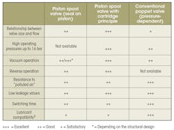
The accompanying table is a valve selection aid. Both spool and poppet valves come with advantages and disadvantages, but the one that best fits your application will depend on your operating conditions. One must consider, for example, if low leakage values and dual pressure operation with vacuum and ejector pulse are your design priorities. Or if you are more concerned with high operating pressures, some leakage may be allowable. Better understanding of your operating conditions will help guide you to choose the right valve for the job.
This file type includes high resolution graphics and schematics when applicable.
