This file type includes high-resolution graphics and schematics when applicable.
One of the most indispensable set of features common to most packaging machines are components that provide linear motion. These components are critical for sealing, conveying, inserting, ejecting, scoring, folding, and carrying out other critical packaging tasks. Most of these linear-motion devices require some way to generate reciprocating motion or index a linear-drive device to fully carry out their packaging tasks.
Even so, in many cases, the packaging application does not warrant complicated designs and interacting subsystems. In fact, when a packaging machine’s linear-motion requirements do not include sensor-dependent indexing or highly accurate slicing or cutting, engineers can often use a simple device called a rolling-ring drive. These less sophisticated, more affordable mechanical devices simplify designs and reduce operating and maintenance costs. This helps manage budgets and assures end users that machines will be relatively easy to operate and maintain.
Rolling-Ring Basics
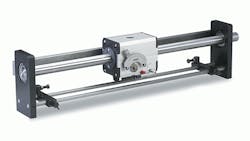
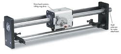
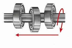
Rolling-ring drives convert rotary motion into basic, back-and-forth linear movement. Thus, the drives become viable alternatives to electronic controls, because they eliminate the need for many additional components such as clutches, cams, and gears (see "Anatomy of a Rolling-Ring Drive" below).
Additionally, rolling-ring drives run on smooth, case-hardened shafts. There are no threads to trap debris or grease. This eliminates the risk of clogs and jams that can cause screw-driven nuts to churn until the screw is ruined. This translates into reduced downtime and savings for rolling-ring drives, as there is no need to interrupt production and stop the system to clean or repair the shaft.
Rolling-ring drives also eliminate backlash from linear drives in packaging machinery. Mechanical power-transmission devices (e.g., leadscrews, gear assemblies, couplings) usually involve joined or mated parts such as meshing teeth in opposing gears. Joined parts always have a little space between them. This space lets lubricants make their way between the parts and reduce wear that would otherwise result if the surfaces were in constant contact. Reducing wear improves longevity.
While the drive is moving, the spaces between parts do not cause any problems. When travel direction is reversed, however, the mated parts must separate and travel in the opposite direction until they mate with the opposing joined part. The distance traveled, no matter how minute, causes backlash in linear motion. The greater the backlash, the more the drive’s accuracy and repeatability are compromised.
There are a variety of mechanical and electronic anti-backlash solutions. For example, preloaded nuts or active cam mechanisms can reduce or eliminate backlash. Other mechanical remedies include flexing gears, shims, and mechanisms designed to preload the gear train. Electronic backlash correction methods include various types of encoders and feedback devices.
A rolling-ring drive transmits mechanical power, but uses a different approach to overcoming backlash. The technique is cost-effective because it does not require an investment in preloads, programming, encoders, and other devices similar to those described earlier.
In a rolling-ring linear drive, the bearing assembly is fixed within the housing (nut). Each bearing in the assembly is held at a specific angle relative to the shaft. The key to a rolling-ring drive's zero backlash is the design of rolling-ring bearings. The bearings are machined so that a central ridge runs around the surface of the inner race. When the rolling-ring drive is placed on a smooth shaft, the ridge of each bearing establishes a point of continuous contact with it. When the shaft rotates, the rotary motion is immediately converted into linear output. There is never any free movement or play between shaft and bearing, even during reversals.
Rolling Rings in Packaging
Let’s say an engineer needs linear motion for a tool head—a simple, repeating reciprocating motion over a fixed distance—to apply glue prior to assembling a corrugated carton. High-end design isn’t needed or justified.
Electronics and controls are fine for precision trimming of Mylar-brand label sheets. However, the simple reciprocating motion needed for some processes, such as scoring boards and running a glue gun back and forth, do not require high-end design and the accompanying complex electronic controls and programming.
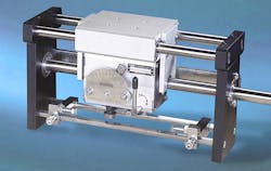
Instead, a rolling-ring drive uses the dynamic bearing/shaft setup described above to convert the smooth, threadless shaft’s rotary-motion input into linear motion. Linear speed and travel direction of the nut are then controlled by pivoting the bearings on the shaft.
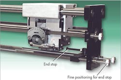
This system becomes a variable-speed linear drive free from programming and electronic controls. Travel speed and direction are mechanically controlled with hardware fittings (end stops) that pivot the bearing assembly in a controlled manner. The shaft does not need to be reversed.
Instead of using a variable-speed, reversible motor such as a servo or stepper motor, a less-costly unidirectional motor may be employed. The drive does not need to be slowed down or stopped when reversing travel direction. That, too, is controlled mechanically without having to adjust motors or controls. Machinery operating time is thereby increased while reducing unnecessary slowdowns and interruptions in production.
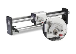
Additionally, in many cases, a drive like this may be powered by a comparatively inexpensive single-speed motor. The linear speed of the drive is mechanically adjustable using a lever control on the drive. Turning the lever pivots the bearings on the shaft, which effectively increases or decreases the linear speed of the drive.
Rolling-ring drives are a simple, elegant way to generate linear motion in packaging machines. Their simplicity—linear output from a rotating shaft without electronics—gives the technology a certain allure from a design standpoint. However, rolling-ring linear motion provides the most noticeable advantage, in terms of efficiency and cost-effectiveness, when used to produce continuous reciprocating motion of the drive head. Using rolling-ring drives for indexing, however, is not always practical.
For example, a picking or grasping tool may need to be positioned over a series of bottles, lowered to grab and lift the bottles, and then moved to where it can lower the bottles into a shipping container. Packaging machinery like this requires custom linear motion of the tool head. Linear speed may need to be ramped up or down and the tool must be indexed—driven backward and forward based on sensor feedback.
Typically, it takes programming, variable-speed motors, and motion-control units to ramp down the drive head before reversal. While a rolling-ring drive can be made to ramp up and down using only hardware fittings through purely mechanical means, it is often not practical given the operating speed and precision of many packaging machines (see "The Need for Complexity in Packaging Equipment"). In such cases, rolling-ring drives can’t compete with electronics and programming for speed and accuracy.
A rolling-ring drive could be fitted with a sensor and linear encoder to monitor positioning data. Then a process controller would signal and control the stepper or servo motor and other components. This is essentially the same sort of control that would be needed with most other linear-motion technologies. Other than the smooth shaft, there is no compelling reason—no significant savings of time or money—to use rolling-ring motion in this situation.
In addition to speed and accuracy, packaging engineers planning on using a rolling-ring drive must also consider how the payload will attach to the drive head. That’s because the bearings inside the nut are installed under factory-specified pressure.
Placing a significant load (weight or overturning moments of force) directly on the nut increases pressure on the bearings. This increase in pressure must be relieved or the specially machined inner races of the bearings will flatten over time, causing the drive unit to lose thrust.
Using a load carrier such as a linear bearing slide removes all forces from the rolling-ring drive. The drive simply pushes against the yokes to slide the load. All weight and forces generated by the load are absorbed by the linear bearing slide. The rolling-ring drive is thus free to do what it was designed to do—push.
When the application permits, engineers can develop simpler, less-costly designs based on rolling-ring linear motion. As mechanical power-transmission devices, rolling-ring drives offer viable alternatives to screw-based machines and other types of linear-motion setups. For repetitive, back-and-forth motion, rolling-ring drives with variable pitch save time and money by eliminating the need for clutches, cams, gears, and other external controls.
Depending on the size of the drive, rolling-ring drives can deliver up to 800 lb. of axial thrust. The only maintenance a rolling-ring drive needs is lubrication of the drive shaft once a month—bi-monthly if use is heavy.
Armed with specific application data, companies supplying rolling-ring drives can determine if a rolling-ring device will improve a packaging machine design. Additionally, suppliers can properly size rolling-ring drives and recommend numerous options to meet a customer’s unique linear-motion needs.
Anatomy of a Rolling-Ring Drive
In the 1940s, German engineer Joachim Uhing invented the rolling-ring drive. Soon after, he founded the Uhing Co. to manufacture and market the devices. After the patents expired, other companies jumped into the market, including Amacoil/Uhing, Cemanco/KMK, and Marldon. There are also numerous Asian knock-offs.
Bob Eisele is Technical Service Rep for Amacoil Inc.
This file type includes high-resolution graphics and schematics when applicable.
