Getting the Right Motor

This article was updated Feb. 20, 2023. It was originally published March 2, 2011.
Engineers are constantly called on to select motors for the applications that will be able to do the task at hand and cost as little as possible over their operational lives. There are many ways to make that selection based on price, performance, manufacturer or even color. But one of the simplest and most effective methods is to is to determine the application’s mechanical and physical requirements, establish electrical requirements that match those requirements and then find a motor that has them.
READ MORE: Economical Motor Sizing for Peak Loads
For example, if an application has limited space or needs to be lightweight, start with a motor that meets those parameters. If necessary, use mechanical means such as pulleys, gears, gear heads and speed reducers to meet the mechanical requirements.
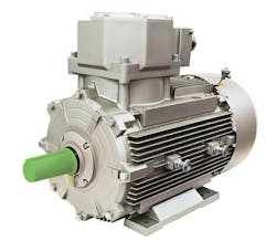
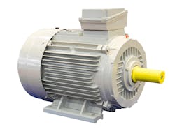
Designers typically first settle on either an AC or DC motor or gearmotor. Gearmotors are ac or dc motors typically used for higher torque and lower rotational speed. Knowing the torque and speed requirements will help in determining if an AC or DC motor is required.
One of the mechanical limiting factors of electric motors is the bearings. Motors that use bearings will typically last longer than those using bushings. They also typically handle more perpendicular loading to the shaft (radial load), whether horizontally or vertically.
No matter how much torque the motor can generate, eventually torque falls off as speed rises or the motor can maintain the given torque only by slowing its rotation. Once these torque-versus-speed qualities are established, engineers can fine-tune the numbers using the previously mentioned mechanical means.
An Example
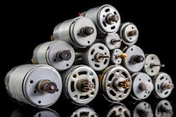
Let’s examine an example of a DC motor that spins at 11,500 rpm with a 1-in.-pitch-diameter pulley. This generates a linear speed of 36,128 ipm (equal to 3,011 fpm or 602 ips). Changing the size of the pulley would alter the speed or torque. However, there are applications that need slower motors with a gearbox. It’s one of those immutable characteristics; as the speed rises, the load capability drops.
Suppose that DC motor will be used to power a conveyor or tangential drive system. Add in the complication that in the application, a spray tip will need to send out a fluid ounce of material over an 18 × 14-in. area using a nozzle which spits out 0.050 gallons/min or 0.1067 oz/sec at 40 psi.
READ MORE: Motor Selection Guidelines for Precision Motion Control
To select the right motor, first find the needed speed and torque. Acceleration will then be found by establishing the time required for the move and solving for shaft speed in rpm.
To get the allotted time, divide the amount of material being dispersed by the rate of dispersion:
1 fl-oz/0.1067 fl-oz/sec = 9.372 sec.
To convert that to linear velocity, divide the length of material by elapsed time:
18 in./9.372 sec = 1.9206 ips.
To find the rotational velocity in rpm corresponding to 1.9206 ips of linear velocity, convert inches/minute to inches/second and convert that to revolutions. In this example, the pulley diameter of 1.003 in. leads to:
1.9203 ips × 60 sec/min × 1 rev/(1.003 in. × π) = 36.57 rev/min or 0.6 rev/sec.
To determine the angular velocity, acceleration and time, assume the motor reaches a constant speed after the equivalent of 1 linear inch of travel. The associated arc length for a rotary system becomes 1 in./π = 0.3183 in.
The formula for determining arc angle can be found in Machinery’s Handbook. To use it, calculate the pulley radius:
1.003/2 = 0.5015.
Using the pulley radius and associated arc length, we get an arc angle: (57.296 × 0.3183)/0.5015 = 36.3655 decimal degrees, or 0.634 radians. (57.296 is a constant from Machinery's Handbook.)
To determine the final angular velocity, divide linear velocity by the pulley radius:
1.9206 ips/0.5915 in. = 3.8297 rad/sec.
To find final angular acceleration, use the equation for acceleration; a = V2/2θ
where θ = arc angle and V = linear velocity. Substituting values for the variables: (3.8297 rad/sec2 )/(2 × 0.6347) = 11.5540 rad/sec2
The final angular time or time needed to reach velocity comes from the relationship: t2 = 2θ/ω. Solving for t gives:
√((2×0.6347 rad)/11.554 rad/sec2) = 0.3315 sec.
Of course, the motor must provide more torque more acceleration rate or a shorter ramp distance is needed. The more torque available, the higher the acceleration in reaching the required velocity.
Inertia
Next calculate the load inertia. When moving objects, the load on the motor is more than just the load of the object being moved. It also included the loads from the pulleys, belts, couplers, and any other device or mechanism between the motor and object being moved. To size the motor, find the total inertia of all these components acting on the motor shaft. Sometimes it is easier to do this using actual weights (transformed into masses) of the devices rather than calculating inertia requirements.
READ MORE: Design Essentials: How to Size a Motor Properly to Avoid Oversizing
In this example, the system consists of a 96.0 oz load, two 1-oz pulleys, and a 0.8-oz belt. Using the general equation for inertia, I = mr2 , where m = mass and r = distance to the rotation axis, the total inertia on the motor is:
I = (96 oz × ( 0.5015 in.)2) + (0.8 oz × (0.5015 in.)2) + ((1 oz × 0.50152 in.) × 2) = 24.8484 oz-in.2
Friction
In this example, two slider rails with four carriage pads carry the load. Each pad has a coefficient of friction of 0.17. The force due to friction is calculated using F = μN, where μ is friction coefficient and N is the force perpendicular to the surface. In this case, N is the mass of the load. So, the equation becomes:
F = (96 oz × (4 × 0.17) = 65.28 oz
This force, in turn, is multiplied by the distance to the rotational axis:
65.28 oz × 0.5015 in. = 32.738 oz-in.
To get total torque, determine the torque needed for acceleration. The initial step is to convert total inertia from oz-in.2 to oz-in.-sec2. This is a simple conversion that consists of multiplying total inertia by a factor read from an inertia/torque conversion table, available from a variety of sources:
24.8484 oz-in.2 × 0.00259 = 0.0643573 oz-in.-sec2.
This figure gets multiplied by the angular velocity and divided by the time needed to reach that velocity:
(0.0643573 oz-in.-sec2 × 3.8297 rad/sec)/0.3315 sec = 0.7435 oz-in.
Finally, add the force needed to overcome friction:
0.7435 oz-in. + 32.738 oz-in. = 33.482 oz-in.
Thus, most of torque for acceleration is needed to overcome friction.
The process for determining the torque needed for a constant load is similar. The only difference in the equation is that linear velocity (calculated earlier) is used instead of angular velocity, and division is by spray time (also calculated earlier) rather than acceleration time. This gives:
(0.0643573 oz-in.-sec2 × 1.9206 ips)/9.372 sec = 0.0132 oz-in.
Now add the force needed to overcome friction:
0.0132 oz-in. + 32.738 oz-in. = 32.751 oz-in.
Once again, most torque goes into overcoming friction. The total torque is the sum of the torque needed for acceleration and for handling a constant load:
33.482 + 32.751 = 66.233 oz-in.
The torque needed for acceleration will not always be about the same as the torque for constant load, as in this case. Do not assume you can just double the torque for constant load and meet the total torque requirement.
Size
This example does not consider deceleration torque. It is not required when solving for maximum torque unless it exceeds the torque needed to accelerate. Another tip: Do not use holding torque to size motors. Holding torque is how much the motor will hold at 0 rpm.
Once this analysis leads to a particular motor, the designer should go back and add the motor-rotor inertia to the calculation and recalculate to verify that the total torque required lies well inside the torque-versus-speed curve. If not, the next bigger motor will be needed. As long as the required torque and speed are kept below the motor profile (with a safety margin) all other concerns are irrelevant.
Other Factors
Keep in mind that side loads (radial loads) and overhang loads are set by the motor manufacturer. They must not to be exceeded unless the goal is to have the motor fail prematurely. Finally, after the motor is installed, empirically measure the actual required torque to move the load and find the side load on the motor. These empirical measurements can verify calculations. In this example, a simple fish scale could give designers a force reading in a pull test to find the amount of force needed to move the load.
Another factor worth considering is the ratio of load-to-rotor inertia. This ratio is important if the motor must accelerate with some precision or stop quickly. It is basically a ratio of how fast a motor accelerates or decelerates its own mass. This, in turn, bears on the accuracy of the motor shaft’s position.
Some motor makers recommend keeping the load-to-rotor-inertia ratio below 5:1. If there are no accuracy requirements other than for starting or stopping the motor, engineers only need to make the speed and torque requirement fall within the motor’s speed-versus-torque profile and add a safety factor. If the rotor-to-load inertia ratio is too high, the motor will over- or undershoot the stop position. Or the shaft might oscillate back and forth before settling at the proper position.
Thus, the need for precision, or the lack of it, determines whether load-to-rotor inertia is significant design parameter. Systems with a 1:1 ratio will have the best precision. Those with a 2:1 ratio or worse will be less so.
READ MORE: Getting the Right Stepper or Servo Motor for Electric Actuators
Consider the inertia from the example and a motor having 0.00143 oz-in.-sec2 of rotor inertia. Converting to the same units (using information from widely available tables) and solving for the ratio yields:
0.00143 oz-in.-sec2 × 386 ips2 = 0.55198 oz-in.2 Then 24.8484 oz-in.2/0.55198 oz-in.2 = 45.
So, the ratio is 45:1.
If need be, a simple way to lower the ratio is to use a motor with more rotor inertia (bigger shaft) or add a gearhead to match as closely as possible the load and rotor inertia. Using a gearhead reduces output shaft speed and boosts torque according to the ratio value. One advantage of gearheads is they handle higher radial loading than would be possible by mounting the device to the motor shaft.
Gearboxes also affect the inertia ratio by a factor of the gearbox ratio squared. To find what gearhead size is needed, solve:
e √(24.8484 oz-in.2)/(0.55198 oz-in.2) = 6.7
This indicates a gear ratio of 6.7:1, rounded to 7:1. Recall that with gearheads, torque rises and output shaft speed drops with the gear ratio. Now size the gearhead to a motor by figuring 66 oz-in. × 1.5 (safety factor) = 100 oz-in. of output torque from the gearhead. This gives 100 oz-in./7 = 14 oz-in. from the motor through the gearbox and 37 rpm × 7 = 259 rpm from the motor.
In this case, the rpm and torque exceed requirements. The controller can fine-tune shaft speed and torque requirements to reach the final values.
John Brokaw was a motion control application engineer at Baldor Electric Co and Norm Ellis was founder of Ellis & Associates.
About the Author
John Brokaw
Sr. Application Engineer
John Brokaw is a Sr. Application Engineer for Valin Corp., a leading motion control and automation company. For more information, visit www.valin.com.
Norm Ellis
Ellis & Associates | Laguna Hills
Voice Your Opinion!
To join the conversation, and become an exclusive member of Machine Design, create an account today!

Leaders relevant to this article: