Authored by: Edited by Stephen J. Mraz Resources: |
Engineers have long used precision gearboxes to let servomotors control heavy loads at high cycle rates in robotic and industrial-automation applications. Over that time, two types of gearboxes have become de facto standards: cycloidal and planetary. Let’s take a look at each.
Cycloidal gearboxes
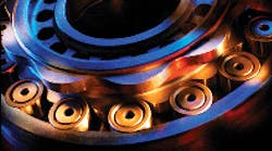
Cycloidal gearboxes or reducers consist of four basic components: a high-speed input shaft, a single or compound cycloidal cam, cam followers or rollers, and a slow-speed output shaft. The input shaft attaches to an eccentric drive member that induces eccentric rotation of the cycloidal cam. In compound reducers, the first track of the cycloidal cam lobes engages cam followers in the housing. Cylindrical cam followers act as teeth on the internal gear, and the number of cam followers exceeds the number of cam lobes. The second track of compound cam lobes engages with cam followers on the output shaft and transforms the cam’s eccentric rotation into concentric rotation of the output shaft, thus increasing torque and reducing speed.
Compound cycloidal gearboxes offer ratios ranging from as low as 10:1 to 300:1 without stacking stages, as in standard planetary gearboxes. The gearbox’s compound reduction and can be calculated using:
where nhsg = the number of followers or rollers in the fixed housing and nops = the number for followers or rollers in the slow speed output shaft (flange).
There are several commercial variations of cycloidal reducers. And unlike planetary gearboxes where variations are based on gear geometry, heat treatment, and finishing processes, cycloidal variations share basic design principles but generate cycloidal motion in different ways.
Planetary gearboxes
Planetary gearboxes are made up of three basic force-transmitting elements: a sun gear, three or more satellite or planet gears, and an internal ring gear. In a typical gearbox, the sun gear attaches to the input shaft, which is connected to the servomotor. The sun gear transmits motor rotation to the satellites which, in turn, rotate inside the stationary ring gear. The ring gear is part of the gearbox housing. Satellite gears rotate on rigid shafts connected to the planet carrier and cause the planet carrier to rotate and, thus, turn the output shaft. The gearbox gives the output shaft higher torque and lower rpm.
Planetary gearboxes generally have single or two-gear stages for reduction ratios ranging from 3:1 to 100:1. A third stage can be added for even higher ratios, but it is not common.
The ratio of a planetary gearbox is calculated using the following formula:
where nring = the number of teeth in the internal ring gear and nsun = the number of teeth in the pinion (input) gear.
Comparing the two
When deciding between cycloidal and planetary gearboxes, engineers should first consider the precision needed in the application. If backlash and positioning accuracy are crucial, then cycloidal gearboxes offer the best choice. Removing backlash can also help the servomotor handle high-cycle, high-frequency moves.
Next, consider the ratio. Engineers can do this by optimizing the reflected load/gearbox inertia and speed for the servomotor. In ratios from 3:1 to 100:1, planetary gearboxes offer the best torque density, weight, and precision. In fact, not many cycloidal reducers provide ratios below 30:1. In ratios from 11:1 to 100:1, planetary or cycloidal reducers can be used. However, if the required ratio goes beyond 100:1, cycloidal gearboxes hold advantages because stacking stages is unnecessary, so the gearbox can be shorter and less expensive.
Finally, consider size. Most manufacturers offer square-framed planetary gearboxes that mate precisely with servomotors. But planetary gearboxes grow in length from single to two and three-stage designs as needed gear ratios go from less than 10:1 to between 11:1 and 100:1, and then to greater than 100:1, respectively.
Conversely, cycloidal reducers are larger in diameter for the same torque but are not as long. The compound reduction cycloidal gear train handles all ratios within the same package size, so higher-ratio cycloidal gear boxes become even shorter than planetary versions with the same ratios.
Backlash, ratio, and size provide engineers with a preliminary gearbox selection. But choosing the right gearbox also involves bearing capacity, torsional stiffness, shock loads, environmental conditions, duty cycle, and life.
From a mechanical perspective, gearboxes have become somewhat of accessories to servomotors. For gearboxes to perform properly and provide engineers with a balance of performance, life, and value, sizing and selection should be determined from the load side back to the motor as opposed to the motor out.
Both cycloidal and planetary reducers are appropriate in any industry that uses servos or stepper motors. And although both are epicyclical reducers, the differences between most planetary gearboxes stem more from gear geometry and manufacturing processes rather than principles of operation. But cycloidal reducers are more diverse and share little in common with each other. There are advantages in each and engineers should consider the strengths and weaknesses when selecting one over the other.
Benefits of planetary gearboxes Benefits of cycloidal gearboxes |
The need for gearboxes Inertia matching. The most common reason for selecting a gearbox is to control inertia in highly dynamic situations. Servomotors can only control up to 10 times their own inertia. But if response time is critical, the motor should control less than four times its own inertia. Speed reduction, Servomotors run more efficiently at higher speeds. Gearboxes help keep motors operating at their optimal speeds. Torque magnification. Gearboxes provide mechanical advantage by not only decreasing speed but also increasing output torque. |
