When electric motors won’t do
When designs call for rotary motion and torque, engineers have the option of specifying electric or hydraulic motors. Electric motors are generally the first choice because they come in a wider variety and typically cost less, and electricity is ubiquitous.
This file type includes high resolution graphics and schematics when applicable.
Electric motors excel in applications that demand high rotational speed and low-to-medium torque output. However, there are cases where hydraulic motors are the best or only option. If the load stalls an electric motor, the windings may burn and permanently damage the motor. Conversely, a hydraulic motor will simply stop without damage under excessive loads, especially when a relief or bypass valve is designed into the circuit. Also, in many outdoor applications, dust, dirt, seawater spray, and the like will attack and destroy an electric motor’s windings, so hydraulic motors are the best bet.
An obvious case where hydraulic motors are the only choice is underwater, because sealing electric motors is costly and requires substantial engineering effort. Properly designed hydraulic motors, on the other hand, have no issues operating under water.
For demanding applications that require extremely high torque, electric motors become too costly and too bulky because of the large number of windings needed. With hydraulics, a large pump can be mounted some distance away, yet supply high-pressure fluid to a compact and powerful motor in the work area. This is a key advantage of hydraulics.
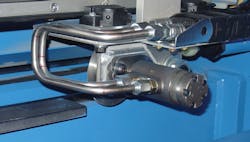
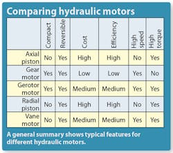
Today, hydraulic motors provide rotary power in a range of equipment. They’re used to turn gears on conveyors; drill, tap, mill, and cut on metalworking machines; and even control undersea cameras. The five main types of hydraulic motors are: axial piston, gear, gerotor, radial piston, and vane. This article focuses on the features and design considerations of commonly used gerotor-style hydraulic motors.
Gerotor motors
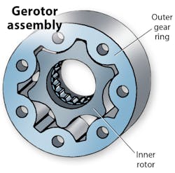
Gerotor motors are usually considered to be low-speed, high-torque (LSHT) motors, but some models spin at over 1,000 rpm — making them high-speed, low-torque (HSLT) devices. The motors have a stationary outer gear that’s part of the housing and a rotating inner gear. The outer ring’s gear teeth mesh with teeth on the rotor, which has one less tooth than the outer ring.
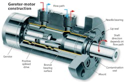
Gerotor motors turn when hydraulic fluid enters the inlet port and exerts pressure on the face of the rotor, causing it to revolve inside the outer ring. The path of the fluid constantly changes as the motor spins. Porting in the motor body and shaft ensures that fluid constantly pushes the back side of the rotor so it continues to turn in the same direction. A linked spindle or shaft transmits motion and torque from the rotor to external devices. The exact position (or timing) of the components is critical to proper operation. The motors are bidirectional, and the direction they turn depends on which inlet port is pressurized.
When selecting motors, engineers must consider two inputs. One is flow rate, typically expressed in gallons (gpm) or liters per minute (lpm). The other is pressure, usually in psi or bar. And there are two outputs of interest, rotational speed (rpm) and torque (lb-in. or Nm).
Before selecting a motor, engineers need to know the rpm and torque the job requires. Rotational speed is generally straightforward, but many designers may not have a good handle on torque requirements. In some cases gearboxes coupled to the motor shaft amplify speed or torque. One benefit of gerotor motors is that slight adjustments to the inputs change the outputs. For example, if the flow rate increases, speed will too. The same relationship holds between pressure and torque, so increasing pressure boosts torque output. However, there are limits. Every motor has an optimal operating range, and it is important to stay within that range to ensure efficient operation and long life.
There are situations to avoid when using gerotor motors. For instance, if pressure is too low, the motors will not turn. Conversely, excessively high pressure could blow seals and cause leaks. If the flow rate is too low, the motor will not spin or transmit torque as all the fluid will pass between the spindle and the inside of the motor body. Too high a flow rate, on the other hand, will waste input energy as the motor generates excess heat due to flow restrictions at orifices and internal porting.
For most applications, it’s advisable to keep the motor at or below 130°F. Gerotor motors can be used in high-temperature applications, like in a heated mold where temperatures can reach 300°F. But such applications require special seals, and hydraulic oil must be cooled to control viscosity and prevent rapid degradation.
Sizing motors
Some systems already have a hydraulic pump. In these cases, the designer needs to find a gerotor motor that matches pump outputs and generates the torque and speed an application demands. In other cases, engineers are working from scratch and have not yet chosen an electric motor or pump. This leaves more options for choosing the gerotor motor that can generate the needed outputs.
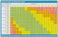
Motor manufacturers produce sizing charts like the Gerotor-motor performance chart shown nearby, and they are essential when selecting hydraulic motors. Shaded cells show regions where a specific motor performs best. Green areas show where the motor is most efficient; yellow areas indicate marginal efficiency. Avoid orange and red areas if possible. (One possible alternative is to consider the same motor with a different-size gerotor.)
For example, consider a case where the pump provides 8 gpm and 1,000 psi. From the chart, the motor will spin at 540 rpm and generate 336 lbâin. of torque. Start-up torque for most gerotor motors is about half of the running torque, or 178 lbâin. in this case. Calculate horsepower using:
HP = (rpm × torque)/63,025
= (540 × 336)/63,025 = 2.88.
So, for this application, the motor would generate 2.88 hp.
One major concern with all hydraulic motors (and pumps, for that matter) is the unavoidable issue of internal leakage. It is the primary cause of efficiency losses. Losses from heat are the second largest concern. Often, more-expensive motors are well worth the higher initial investment when one considers energy costs involved with using lower-priced but less-efficient motors.
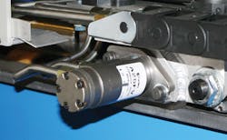
Most gerotor motors have a number of options for mounting flanges, shafts, and seals. In applications where space is tight, some motors can even mount just using the ports. Motor manufacturers offer many common shaft options as well. Usually, a short or long keyway works for most tasks. Other times, flats are machined on the shaft and setscrews lock a device to the motor. When transmitting sizable torques, shafts with splines on the ends are often recommended.
System considerations
The motor is just one part of a hydraulic system. Other components, such as pumps, hoses, and filters all influence overall performance. For example, if the motor is far from the pump, pressure loss becomes a consideration. Two ways to combat pressure loss are by using larger-diameter hose and tubing, or simply increasing pressure at the pump. In addition, it is best to limit, where possible, bends and orifices in fluid connectors and conductors, as they add to pressure losses. Filtration often gets neglected, too. That neglect leads to contaminated fluid and causes excessive wear and tear on all system components, including the motor.
Not all fluids act the same, however. In locations that demand fire-resistant or explosionproof equipment, water glycol is sometimes used. Be aware that water glycol causes motors to generate a bit more heat because lubricity is lower than with other fluids. Other situations may call for a motor to run on a lightweight transmission fluid. Here, engineers must account for the fluid’s lower viscosity as leakage can easily get out of control.
Hydraulic gerotor-motor manufacturers offer many material options. Most common is steel, widely used thanks to low cost and high durability. When the overall weight of a design is important (for example, in hydraulic hand tools) aluminum is the best option.
When corrosion resistance is critical in rugged environments, a coating is usually applied to the hydraulic motor. Depending upon the application, common coatings include nickel or chrome plating, or even just a simple coat of paint.
Donald L. Hahn
Component Technology Manager
Lamina Hydraulics
Anchor Lamina America Inc.
Farmington Hills, Mich.
Resources:
Lamina Hydraulics, www.anchorlamina.com
