How to Pick Motors for Linear Motion
Download this article in .PDF format
The easiest way to design a linear-motion system is to add components one by one. Then, step-by-step calculations relate input to power dissipated moving a load in a specific amount of time.
Linear systems drive everything from inexpensive seat movers in passenger vehicles to precision laser cutters and CNC machines. All move loads through a linear distance in a specific amount of time.
One approach for designing a linear system is to list basic requirements, add components one by one, and define every force interaction along the way.
Define the problem
To begin a linear design, determine the mass of what moves and how fast it goes from A to B. We work in SI units, as they eliminate multiple conversion constants and can always convert back into English units. For example, assume we’re choosing a motor for a simple linear-rail mechanism that moves a load:
Load's mass = 9 kg
Mass orientation: Vertical
A-to-B move distance and time = 200 mm in 1.0 sec
Dwell time = 0.5 sec
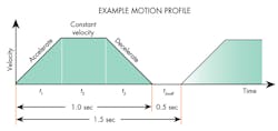
Move profile = 1/3-1/3-1/3 trapezoid–controlled acceleration and deceleration
Rotary-to-linear conversion = TFE-coated leadscrew Ø8 mm and 275-mm long
Load support: Linear ball rail and TFE-coated guide rails with a friction coefficient μ = 0.01
Overall size: Limited to the smallest volume possible
Drive architecture: Must be simple, as this is a cost-sensitive application
Drive control: Four-quadrant operation with encoder feedback
Drive power supply = 32 Vdc, 3.5 Arms, 5.0 Apeak maximum output
Worst-case ambient temperature = 30°C
Because force = ma (where a = acceleration due to gravity = 9.81 m/sec2), the 9-kg mass lifted against gravity requires a force of 88 N.
Sizing: Just the beginningThis article explains how to size a motor for a relatively simple single-axis linear-motion application. What don’t we cover here? Sizing motors for complex designs. The motor-sizing principles we outline are applicable to X-Y tables and multiaxis pick-and-place machines. However, every axis in these designs requires independent analysis of load demands. Choosing a safety factor so the machine lasts for its intended life. A design’s number of useful cycles depends on motor size, as well as the machine’s mechanical elements including the gearbox and leadscrew assembly. Accounting for positioning accuracy, resolution, repeatability, maximum roll, pitch, and yaw. Only linear-motion systems that account for these fully meet application requirements. |
1. How much power is needed to move the load in the required time?
Calculating minimum power output to translate the load provides a starting point for specifying the rest of the system's components. For our example, this is the average power needed to lift the 9 kg from A to B in 1 sec.
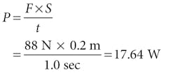
where P = power, W; F = force, N; S = linear distance, m; and t = time, sec.
Note that power calculated here is less than peak power (or instantaneous power during the move profile) to accelerate and decelerate. Likewise, power calculated here doesn’t factor in extra power to overcome system losses such as friction. We’ll calculate the motor-shaft power for that in a later step.
Pick the motor
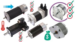
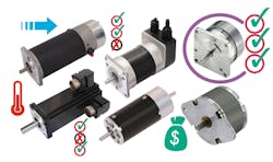
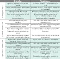
2. What motor technology is best for this application?
As outlined in our original parameters, the final design must be inexpensive and have simple drive architecture. Stepper motors satisfy both of these requirements. However, minimizing this machine’s overall volume is also important, so a stepper isn’t recommended: The 17.64-W minimum power requirement at the load (not including system losses and instantaneous peak power) would necessitate a large stepper. A brushless motor solves the problem of design footprint, but adds cost and complicates the drive architecture.
The third option — a dc-brush gearmotor with an in-line planetary gearhead — provides a small footprint, simplified drive, and relatively low cost. Adding a leadscrew for rotary-to-linear conversion keeps gearmotor output speed at around 1,000 rpm, which reduces generated heat at the leadscrew and nut-thread interface.
Gearmotor output
3. What’s the velocity, reflected inertia, and reflected load at the gearmotor output shaft (acting as the leadscrew input)?
Step one: Calculate the peak linear velocity of the application with its 1/3-1/3-1/3 motion profile:
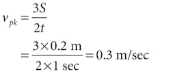
where vpk = peak linear velocity, m/sec.
Step two: Calculate the minimum pitch needed to keep the leadscrew speed at about 1,000 rpm:
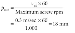
where pmin = minimum leadscrew pitch, m.
For one typical product, the closest pitch in an 8-mm screw diameter is 20.32 mm.
Step three: Calculate the peak shaft speed of the leadscrew (in rad/sec) for a linear velocity of 0.3 m/sec:
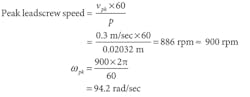
The leadscrew we select is TFE coated, 275-mm long, 8 mm in diameter with a 20.32-mm pitch, and paired with a freewheeling nut. Assume the leadscrew efficiency, ηs, is 86% and its inertia, Js, is 38.8 × 10⁻⁷ kg-m2.
Step four: Determine the total reflected inertia, JT, back from the load to the leadscrew shaft:
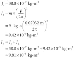
where JL = reflected load inertia, kg-m2; m = mass, kg; and p = leadscrew pitch, m.
Step five: Determine the shaft torque needed to accelerate the load inertia Ta:
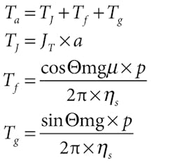
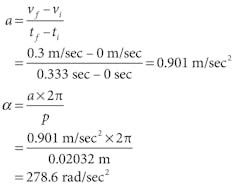
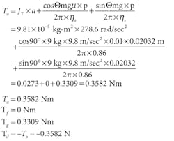
where TJ = torque required to overcome load inertia, Nm; Tf = torque required to overcome friction, Nm; Tg = torque required to overcome gravity, Nm; a = linear acceleration,
m/sec2; Θ = load orientation, with horizontal = 0° and vertical = 90°; m = mass, kg; g = gravitational constant = 9.8 m/sec2; p = leadscrew pitch, m; vf = final linear velocity, m/sec; vi = initial linear velocity, m/sec; tf = final time, sec; ti = initial time, sec; and α = angular acceleration, rad/sec2.
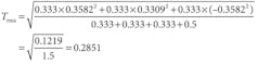
4. What is the RMS torque Trms required at the gearmotor shaft (acting as the leadscrew input)?
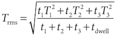
The 1/3-1/3-1/3 motion profile over 1 sec means that 0.3582 Nm is applied for 0.333 sec, then 0.3309 Nm is applied for 0.333 sec, then –0.3582 Nm for the remaining 0.333 sec.
The RMS torque requirement predicts the gearmotor’s thermal rise. The motor is thermally overloaded if the RMS torque falls outside the safe or continuous-operating area of the dc-motor curve.
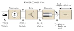
Define total power
5. What are the first-approximation power requirements to drive the leadscrew shaft?
6. What are the final load parameters at the leadscrew input shaft (acting as the gearmotor output shaft)?
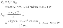
Trms = 0.2851 Nm; Tg= 0.3309 Nm; Ta= 0.3582 Nm; ωpk = 900 rpm = 94.2 rad/sec; Ppk = 33.74 W; and Pavg = 20.47 W.
The gearmotor applies torque to the leadscrew shaft. First it must transmit peak acceleration torque to accelerate the mass against gravity — and get the leadscrew to its steady-state speed of 886 rpm (rounded to 900 rpm.) The gearmotor must then supply enough steady-state torque to move the mass against gravity at constant velocity. Finally, during deceleration the gearmotor must supply a negative torque to stop the load in a controlled manner. All this occurs in the 1.0 sec before the motor stops and dwells for 0.5 sec. After this dwell, the gearmotor reverses and moves along the same motion profile to bring the load back to the starting point.
Choose gears
7. What motor-gearbox combination (gearmotor) meets the load parameters?
Several gearmotor options will work. The best choice depends on the design’s total footprint, audible noise limits, and price, which we won’t cover here. The maximum torque capability of the gearbox must exceed the peak torque required by the application; otherwise, the gearbox will be damaged.
RMS torque required at our design’s leadscrew input shaft is 0.2851 Nm. Average and peak powers required at the leadscrew shaft are 20.47 W and 33.74 W. Here, a 21-W motor won’t meet the load requirements because it won’t have the extra power to overcome system losses. (Remember that leadscrew shaft power comes from the motor through a gearbox, so the motor must supply enough power to overcome gearbox efficiency losses.) The motor must also have extra power if the design needs a built-in safety factor.
A good first pick is a relatively small-diameter brush-type dc motor with a rated (continuous) output power of 37 W. Assume:
Winding voltage V = 24 V; continuous torque Tc = 0.0812 Nm; speed at continuous torque nCT = 4,370 rpm; current at continuous torque IC = 2.36 A; continuous output power PC = 37 W; torque constant KT = 0.042 Nm/A; voltage constant KE= 0.042 V/rad/sec; terminal resistance = 1.85 Ω; NL current I0 = 0.180 A; NL speed n0 = 5,230 rpm; peak current Ipk = 13 A; peak torque Tpk = 0.5422 Nm; and thermal resistance Rth = 11°C/W; motor insulation = Class F (to withstand up to 155°C).
Remember that our initial application parameters indicate we have a 32-Vdc drive power supply available. Therefore, choosing a 24-Vdc motor winding makes for some voltage “headroom” — about 33%. This allows the drive to supply an additional voltage "boost" during intermittent peak-power events. A lower-voltage motor winding would also work, but would require more current from the drive for a given load. A 24-V motor winding allows for higher speeds while minimizing load current.
Now use the motor data above and the load parameters at the leadscrew shaft to choose an appropriate gearbox. For this application, an in-line planetary gearmotor is most suitable. After confirming that such a planetary gearbox is compatible with the motor we picked, we use a few quick calculations to determine that a 5:1 reducer can safely output a maximum torque of 2.47 Nm. That easily exceeds the application’s 0.3582-Nm peak-torque requirements.
Assume our 5:1 planetary gearbox has a published efficiency of 0.90. At the motor output shaft (reducer input) it requires:
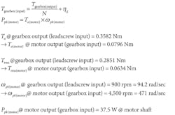
where N = gear ratio; ηg = gearbox efficiency; Ppk = peak power, W; Ta(motor) = torque required at motor shaft during acceleration, Nm; Trms = RMS torque required over the total duty cycle, Nm; Trms(motor) = RMS torque required at the motor shaft, Nm; ωpk = Peak angular velocity, rad/sec.
Our chosen 24-Vdc motor is rated for a continuous output torque of 0.0812 Nm and a continuous current of 2.36 A. The RMS torque requirement of the application is 0.0634 Nm. As a first approximation, this motor-gearbox pairing safely meets the RMS torque requirements. Note the continuous rated power output of the motor is 37 W and the peak (intermittent) power required for the motion profile is 37.5 W. But this motor is still sufficient because the application's RMS torque requirement is still within the motor's safe operating limits.
Spec the drive
8. Can the drive and power supply meet the requirements of the load?
First, calculate the required peak current:
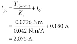
where Ipk = peak current, A, and KT = torque constant, Nm/A. Then calculate the required RMS current:
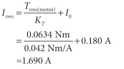
where Irms = RMS current, A; then calculate the minimum bus voltage required for Ppk:
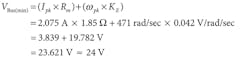
where VBus = drive bus voltage (dc), V and Rm = motor terminal resistance, Ω. Based on these calculations, the drive and power supply should meet the dynamic load requirements of the motion profile. Drive power-supply input is 32 V and maximum dc bus voltage is roughly 30 V, leaving plenty of margin above the minimum bus-voltage requirement of 24 V. Maximum current of the drive and power supply also meet the application's RMS current and peak current demands.
Motor type and sizeNo motor type is best for all applications but there's usually one particularly suitable motor for each design. For most incremental-motion applications the choices are stepper, brush-dc, or brushless-dc motor. Some complex designs use linear motors to directly drive the load and eliminate intermediate leadscrews, ball screws, gearboxes, pulleys, and other mechanical power converters. These direct-drive motors maximize accuracy, repeatability, and positioning resolution but are more costly and complex than designs based on rotary motors. Plus, machines based on rotary motors satisfy most linear-motion requirements. All motors (ac and dc) use the interaction of magnetic fields to generate output torque, but dc-stepper, brush, and brushless servomotors use a dc power supply. For linear-motion applications, a fixed source of dc can’t be applied directly to the motor windings; electronics must control the winding current (related to output torque) and voltage (related to output speed). After determining which motor type is best, choose a frame size with enough torque, speed, and power to accelerate the load quickly enough to satisfy design requirements. The motor must also generate enough torque to overcome the effects of friction (in the design’s mechanical transmission) plus gravity without overheating. |
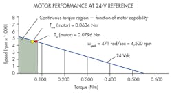
A comparison of the performance plots at 24 and 30 V tells a more complex story. Our application's load points are the same on both plots. However, a 24-V condition may or may not deliver the required maximum velocity of 4,500 rpm — as points for both acceleration torque Ta(motor) and RMS torque Trms(motor) fall close to the 24-V load line. In fact, our calculations indicate we need a minimum bus voltage of 24 V to meet the application's peak requirements. A 24-V bus voltage may initially work, but there's no safety factor — so any mechanical wear in the system over time could cause speed to fall below 4,500-rpm. In contrast, 30-V bus voltage from the drive provides plenty of safety margin to help deliver peak velocities of 4,500 rpm.
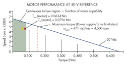
Consider the plot of the motor under a 30-V reference and notice how Ta(motor) and Trms(motor) both lie within the shaded region on the plot. Trms(motor) must remain below the continuous torque rating of 0.0812 Nm. However, in many applications Ta(motor) moves outside the continuous-torque region. This is perfectly acceptable because acceleration torque is factored into the RMS torque. Here it's just a coincidence that both Ta(motor) and Trms(motor) fall within the plot's shaded area. The point to remember is that it’s absolutely necessary for RMS torque to fall within the shaded region of the curve: Otherwise, thermal overloading results.
Check for heat
The prime mover — the dc gearmotor — must be sized to meet dynamic load conditions encountered throughout the motion profile. (This contrasts sharply with sizing a motor for continuous operation at an unchanging load point.) What complicates the issue are incremental positioning applications that make frequent starts and stops with duty cycles that make the motor work harder during periods of controlled acceleration and deceleration. The main concern in these situations is that the motor remains below the maximum temperature rating.
Calculations based on RMS torque and current estimate the motor's overall temperature and temperature rise for a given motion profile:
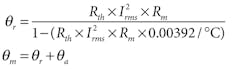
where Ѳm = motor temperature, °C; Ѳa = ambient temperature, °C; and Ѳr = temperature rise, °C.
9. What is the motor's (estimated) worst-case temperature under load at an ambient temperature of 30°C?
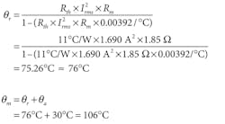
where Rm = motor terminal resistance, Ω and Rth = thermal resistance, °C/W. With a 76°C rise based on the RMS load and a worst-case ambient temperature of 30°C, the motor stabilizes at about 106°C. A Class-F rated (155°C) motor allows a safety margin of 49°C. However, if any portion of the motion profile is altered — total move distance, acceleration and deceleration rates, dwell time, and so on — the equivalent motor load (both peak and RMS) also changes. Repeat the analysis using the revised motion-profile parameters to verify the motor remains within safe temperature limits.
Design caveat
Note that the approach outlined here is a first-approximation analysis. All systems should be tested using actual load conditions. Steady-state temperature should be determined using thermocouples in several locations on the motor. Current into the motor and voltage across the motor should also be measured and recorded.
Motors operate differently under elevated temperature; motor resistance, torque constant, and voltage constant all change under actual operating conditions. This spurs corresponding changes in peak current, RMS current, and bus voltage requirements. Therefore, always contact the motor's manufacturer for advice and test all systems under real-life operating conditions.
Edited by Elisabeth Eitel, [email protected]
Resources: Leadscrew calculations in this article are based on values from a Kerk screw chart
Motor calculations are based on values for a Pittman 9237 motor and G30A gearbox
Voice Your Opinion!
To join the conversation, and become an exclusive member of Machine Design, create an account today!

Leaders relevant to this article: