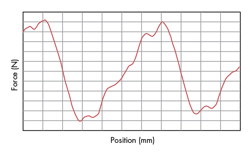
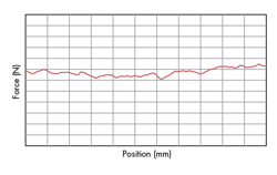
Ironless linear motors have had a clear advantage over ironcore linear motors in many applications for one clear reason: they’re not subject to cogging. “Cogging” is a term used to describe non-uniform velocity. It can appear as a jerky motion, especially at slow speeds. It happens because of the magnetic attraction between the steel teeth of the motor forcer (stator) and the magnet track that it rides over. Cogging limits the smoothness of motion for systems using ironcore motors, allowing them to only be used in applications that require motion from one point to another. Ironless linear motors do not have steel stator teeth in their design, therefore cogging is eliminated, allowing the motor to achieve smoother uniform velocities. (It should be noted that since these are linear motors, there is no rotary motion involved.)
There is a solution to cogging for those manufacturers preferring ironcore motors in their applications. Why wouldn’t they, after all? Ironcore motors use half the magnets of equivalent ironless motors, which helps lower the price of the application. In addition, the higher magnetic flux creates much more force relative to the size of the motor.
Ironcore linear motors are simply rotary motors cut and unrolled; they contain the same parts but in slightly different relationships. The lamination cage becomes the comb-shaped back iron. The windings still reside inside slots in the lamination assembly. The shaft with magnets bonded to its circumference becomes a flat plate with magnets on the surface. In a typical design of ironcore motor construction, the magnetic forces designate the position of the motor between the lamination teeth and the permanent magnet assembly. A horizontal component of the net force will move the lamination assembly. As the coil moves relative to the magnets, this force will change. This is what causes cogging in an ironcore motor. There is a vertical component where magnetic attractive forces exist between the coil and the magnet track. This force must be able to be absorbed by the bearing structure. This is seen as bearing preload.
Parker Hannifin ironcore motors use a fractional winding technique. In fractional windings, the teeth do not correspond equally to the magnets, so the horizontal component of the net magnetic force from the inner teeth will be lower. Many of them will cancel each other out. However, the cogging forces from the leading and training edges remain. The vertical component of the magnetic force also remains, however it is much more constant. This results in smaller variations in bearing preload.
Cogging Force
The cogging force can be measured by moving the motor at a constant velocity and recording the current output of the driving amplifier versus time. Knowing the velocity and the motor’s force constant, force versus position can be plotted. For example when the Parker Trilogy R10-1 motor is moving at 2.5mm/s. approximately 35N of the force is due to mechanical-bearing friction.
Traditional Means of Reducing Cogging
Cogging is not unique to linear motors; rotary motors have the same problem. There are several methods traditionally used to minimize cogging that can be employed in linear motors. These include:
- Skewing the magnets;
- Shaping the magnets; and/or
- Skewing the slots in the laminations.
All of these reduce cogging by intentionally misaligning the laminations and magnets. This softens the transitions of the lamination teeth from one magnet to the next and reduces cogging, but it also reduces the motor’s force output and efficiency because the windings and magnetic fields are no longer optimally aligned.
Anti-Cog Technology
Parker’s anti-cog technology does not use skewed magnets or any other method that compromises motor efficiency. It uses destructive interference. Additional features are added to the lamination assembly that produce an opposite and equal cogging pattern. These features are called anti-cog blocks. Because a fractional winding is used and the cogging forces from the inner teeth all cancel each other out, the same size and shape anti-cog blocks can be used regardless of the length of the lamination assembly. Anti-cog blocks only have to compensate for the cogging from the leading and trailing edge of the lamination assembly.
The anti-cog assembly is a parallelogram made using a proprietary powdered metal material and process. The material, shape, and manufacturing process are all carefully controlled to ensure that the cogging force of the anti-cog assembly equals that of the lamination assembly. By reducing cogging, an ironcore motor may be used in place of an ironless motor. Advantages are that ironcore motors produce more force relative to size vs. ironless, so a smaller motor can be used. Also, ironless motors use two sets of magnets on a U-shaped track while ironcore has one set of magnets that can be significantly less expensive.
Ironcore linear motor coils have preferred positions relative to their magnets. This causes disruptive cogging forces and has traditionally limited their performance in applications requiring smooth operation. Methods such as skewing the magnets or slots and shaping the magnets can reduce the cogging, but at a cost in motor efficiency. The use of a fractional winding simplifies the implementation of the anti-cog technology and results in a much more constant attractive force for more consistent bearing preload. Anti-cog technology virtually eliminates cogging and enables ironcore motors to be used in applications where only ironless motors would have been considered before.
Jeff Nazzaro is the Gearhead and Motor Product Manager at Parker Hannifin Corp.—Electromechanical Automation.


