Designing In-Hub Brushless Motors
This file type includes high resolution graphics and schematics when applicapable.
In-hub motors are traction motors in that they change rotary motion to linear motion. They are actually a special case because they are part of the wheel itself instead of being attached to the wheel through gearing. This limits these direct-drive motors to a size that will fit inside the wheel.
In-hub motors have been widely used in bicycles and scooters and are now expanding into small electric transport carts and small recreational vehicles. Some early in-hub motors for bicycles and scooters had a gearbox as part of the In-hub assembly. The in-hub motors discussed here are direct-drive motors with no gearbox. The direct-drive motor will be a low-speed motor. Without the mechanical advantage of gearing, the motor size is limited by the tire ID. This size limit will also limit the torque that con be produced.
Nevertheless, it looks as though in-hub motors will have a bright future where there is a need for smaller traction motors. They probably will not replace traction motors in locomotives or trucks, but smaller applications will be fair game. The absence of a gearbox and the accompanying potential for oil leakage will make them attractive for use in autonomous or guided carts used to move supplies in hospitals and factories. These applications also will be required to operate on batteries and as battery technology improves, the range of applications for in-hub motors will also increase.
Selection process
As with most electric motors, the required load and speed dictate the size of an in-hub motor necessary to handle a given application. The first task in the selection process will be to convert the maximum linear load and speed into rotational speed and torque needed at the wheel. If more than one wheel will drive the load, the total load can be divided by the number of driving wheels.
The in-hub motor is a direct-drive motor, so the effective gear ratio is the diameter of the tire. Tire diameter will define the motor output needed. With the output determined, the next step is to determine whether a motor can be designed to fit inside the wheel in question. The length of an in-hub motor should not be much longer than the width of the wheel. Thus, the wheel size without the tire generally dictates the dimensions available for the motor.
Unfortunately, several complications pertaining to motor characteristics can make it hard to predict the motor output given the allowable size. For example, the type of magnets used and the geometry of components in the magnetic circuit affect the motor design. So today, the design process for an in-hub motor still relies on simplifying some design criteria from experience.
The in-hub motor can take many forms but the most common is that of a brushless permanent-magnet (BLPM) configuration. One benefit of BLPM devices is that they need no field winding to generate flux as for induction or dc-brush motors. The permanent magnet produces a constant field that interacts with the field produced in the stator windings. Consequently, the electrical input to the stator windings solely controls the motor speed.
Specifically, the input voltage is directly proportional to a constant multiplied by the motor speed measured in rpm. The torque output of the motor is directly proportional to a constant multiplied by the motor current.
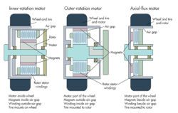
For use as a hub motor, PMBL motors can be built in three different configurations. The first, and least practical, is as an axial-flux motor, where the stator windings are typically sandwiched between sets of magnets. The problem is that axial-flux motors must be physically large to get performance comparable to that of conventional radial designs (or they must use expensive rare-earth magnets rather than inexpensive ferrites). The larger physical size eliminates this design from consideration in most in-hub applications, which typically need a relatively small motor with a large output torque.
The other two configurations are both radial designs with the motor magnets bonded to the rotor; in one, the inner rotation motor, the rotor sits inside the stator, as in a conventional motor. In the other, the outer-rotation motor, the rotor sits outside the stator and rotates around it. The application of hub motors in vehicular uses is still evolving, and neither configuration has become standard. So it is worth comparing these two styles.
The outer-rotation motor will have the rotor formed as the tire rim and the tire will directly mount to the motor rotor. In most applications, the outer-rotor style would be preferred because the rotating part could mount directly to the wheel and tire. However, this would only be advantageous when working with loads small enough that the length of the motor would not exceed the width of the wheel. A motor longer than the width of the wheel would protrude from the wheel and could diminish the vehicle’s turning radius and other handling qualities. Also, the motor only clears the running surface by a distance slightly larger than the tire profile height. Thus, a motor that protrudes beyond the wheel is potentially subject to damage from road debris or other such factors.
In contrast, an inner-rotation motor has the stator winding on its outer shell. The rotor sits inside the stator and connects to a shaft. Spokes typically connect the wheel to the rotor shaft. The advantage of this design is that there is typically appreciable clearance between the running surface and the motor housing.
One major issue affecting the design of in-hub motors is cost. Most of the motor cost will be in the magnets and the copper. Recall that for an outer-rotation motor, the rotor diameter exceeds that of the stator. Thus, the rotor magnets will be large compared to those on an inner-rotation motor where the rotor fits within the stator. But the volume of copper in the windings of an outer-rotation motor would be less than that of an inner-rotation device.
Also, the magnets on an outer-rotation motor lie near the motor’s outer diameter. This allows a larger radius for the development of torque and reduces the amount of force needed at the air gap. Because there is a larger volume of magnetic material the magnets need not be high energy and may, thus, be made from less-expensive bonded rare earth material. Bonded rare-earth magnets cost about half that of sintered versions.
Conversely, the inner-rotation motor has a small magnet volume but a larger volume of copper stator windings relative to an outer-rotation motor. Because there is less magnet material, the motor typically requires high-energy (and high cost) sintered rare-earth magnets.
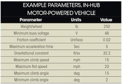
An example helps give a feel for how design decisions come about in an in-hub motor project. Consider a particular case where the design parameters are listed in the accompanying table. Assume these are parameters for one wheel. (Thus, the total vehicle weight is 1,000 lb.) A design can handle higher loads by installing in-hub motors in additional wheels.
The vehicle of interest reaches a maximum climb speed when accelerating up the 15° incline and reaches its maximum speed on a flat surface. The vehicle would monitor power delivered to the motor to keep power from exceeding a maximum value. As the acceleration torque drops or the slope of the hill declines, the speed can rise toward the maximum without exceeding the maximum power.
Assume these in-hub motors will operate on 48-Vdc and have a peak current of 100 A line-to-line in a trapezoidal drive mode, where feedback from Hall-effect sensors report the location of the rotor to the motor drive. The motors could also be driven with a sine-type drive and still provide essentially the same performance.
We know speeds needed and the voltage available, so we can determine the motor voltage constant as a function of the wheel diameter. Suppose we allow 20% of the voltage to go into the motor IR drop. We can then calculate the maximum motor resistance allowed using the motor equation
V = I × R + Ke × S
where S = motor velocity, rad/sec; Ke = motor voltage constant, V/rad/sec; V = motor voltage, V; I = motor current, A; and R = motor resistance, Ω. In this case, we calculate a maximum winding resistance of 0.18 Ω by considering the case where S = 0. We calculate Ke by knowing the desired speed, S, and considering the no-load case where I = 0. The motor voltage constant will also change as the wheel diameter changes because of changes in wheel circumference.
We’ll consider three conditions. The first consists of acceleration to 75% of the maximum speed up the maximum incline. The second is while the cart accelerates on a 2° incline to maximum speed. The third is while running at the maximum speed on the 2° slope with no acceleration. We use the 2° incline for the maximum speed case simply because most flat surfaces are not entirely flat. The power needed will be a function of the forces necessary using the parameters of the cart accelerating and running on a surface.
Recall that the power needed to move up an incline can be expressed as the necessary speed multiplied by the torque from the motor speed-torque curve. In this particularly case, the power to accelerate up the 15° slope calculates to 3 kW, the power to accelerate up the 2° slope calculates to 1.8 kW, and the power to run at a constant speed on the 2° slope calculates to 400 W. Thus, dissipated power changes by over a factor of seven in these different slope scenarios, with only a small amount of power needed on a flat surface. Thus, it is hard to come up with an average power because of the drastic changes in operating conditions.
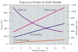
The best way to find an average power is to set up a test that will yield a consistent value. If required power stays constant (implying load is constant), the torque necessary will diminish as wheel diameter rises. The accompanying figure of Torque as a function of wheel diameter shows the torques for the three conditions as a function of the wheel diameter, assuming a given constant load. For the sake of an example, we pick a wheel diameter of 12 in. and a motor OD of 10 in.
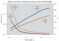
Given a wheel and motor diameter, we next determine a minimum motor length to get the power needed. Specifically, we compare outer rotation and inner-rotation motors necessary as a function of the winding stack length. An accompanying figure of Motor constant, resistance versus motor stack length shows the motor constant and resistance of both styles of motor as a function of the motor stack length. We determined earlier that the maximum stator resistance was 0.18 Ω. For an outer-rotation-style motor, we can meet this value with a stack length of 1.5 in. using bonded neodymium magnets. The outer-rotation motor will need a 2-in.-deep stack though it employs stronger sintered neodymium-magnet material.
Another factor is the motor constant which is a measure of the motors thermal capacity. The units of the motor constant are torque divided by the square root of dissipated power. The accompanying figure also shows that the outer-rotation motor will have a higher thermal capacity than the inner-rotation motor. This is not a big advantage because the inner-rotation motor will have the winding attached to the motor OD and will have a better thermal path to get heat out of the winding.
All in all, this analysis shows that the outer-rotation motor gives a simpler design in that the wheel/tire is part of the motor and the motor can have a shorter stack than the inner rotation case. The shorter magnet and stator in the outer-rotation motor would also cost less.
This analysis assumes an air-gap flux density of 5.5 kG for the outer-rotation motor using bonded neodymium magnets and an air-gap flux density of 8 kG in the inner-rotation motor using sintered neodymium magnets. These results would change depending on the grade of magnet but the results still would be similar to this example.
Also note the motor constant rose with stack length in both of these motors. This implies motors with longer stack lengths would be more efficient but the motor cost would also rise.
Resources:
Voice Your Opinion!
To join the conversation, and become an exclusive member of Machine Design, create an account today!

Leaders relevant to this article: