Could Magnetic Gears Make Wind Turbines Say Goodbye to Mechanical Gearboxes?
This file type includes high resolution graphics and schematics when applicable.
Bad things can happen when the mechanical gearbox in a megawatt-scale wind turbine gets overstressed. An unexpected wind gust can drive turbine blades hard, so hard that the torque on the gearbox they’re connected to exceeds design parameters. The result: A multiton gearbox that must be detached and brought down with a construction crane for repairs. The whole operation is expensive and puts the wind turbine out of commission for days or weeks.
No wonder, then, that wind-turbine makers are interested in ways of capturing wind energy without the need for mechanical gearboxes. One solution now getting a lot of attention is magnetic gearing. There is no physical connection between two magnetic gear rotors. Their motion couples through a modulated interaction between the flux generated by magnets on input and output rotors. If the torque on the input exceeds maximum design levels, there are no broken teeth or other mechanical problems. The magnetic gears simply slip. Moreover, it looks as though magnetic gearboxes could be about the same size as mechanical gearboxes with the same ratings, but would be lighter.
One of the hotbeds of magnetic gear research is at Texas A&M University’s Advanced Electric Machines and Power Electronics Lab in College Station. There Professor Hamid A. Toliyat directs a group working on various types of magnetic gears and actuators. The wind-turbine maker Vestas, Demark, has been among the Lab’s supporters. Now the Office of Naval Research and the Dept. of Energy are sponsoring magnet gearing and actuation projects in wave energy and ship propulsion.
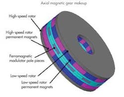
Toliyat’s group has worked on three basic configurations of magnetic-gear designs: an axial gear, a radial gear, and a trans-rotary gear. Axial designs have a configuration resembling that of a clutch pack or pancake motor. They consist of two disks each containing alternating positive and negative magnets with a modulator disk in between. The low-speed disk, or low-speed rotor, contains a magnetic pattern geometry that alternates more quickly than that of the high-speed rotor. Thus there are more pole pairs on the low-speed rotor than on the high-speed rotor. The gear ratio is a function of the number of pairs on the two rotors and the air-gap fluxes they produce. The amount of torque transmitted is a function of the flux linkages between the two disks and is affected by the size of their magnets. So as the size of the magnetic areas grows smaller — as when cramming in more pole pairs or reducing the diameter of the rotors — there is a point of diminishing returns as radial-flux leakage becomes more of a problem.
Axial magnetic gears are probably the most challenging basic topology, say researchers in Toliyat’s group. “There can be huge axial forces on the bearings so there are a lot of issues,” explain Texas A&M Ph.D. students Matt Johnson and Siavash Pakdelian. They also say axial designs are tougher to analyze than those of other configurations because an accurate analysis requires a full 3D model whereas other topologies can be simplified for analysis using symmetry. And as currently constructed, axial designs would be more difficult to manufacture than magnetic gears using radial or trans-rotary configurations.
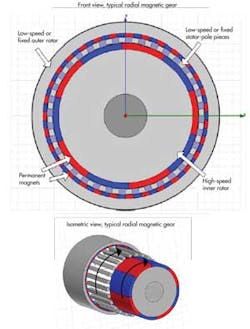
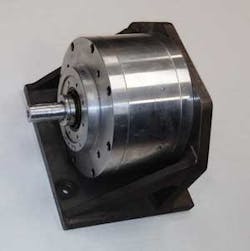
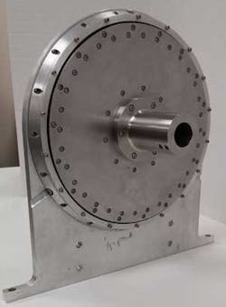
Manufacturing considerations are among the reasons why industry seems to have more initial interest in building radial magnetic gear designs than axial designs. Radial magnetic gears have a configuration that resembles that of a synchronous motor. A typical topology uses a high-speed inner rotor concentric with a low-speed outer rotor. The two rotors are separated by a stator typically composed of electrical steel bars. As with axial magnetic gears, the stator bars modulate the flux between the permanent magnets on the input and output rotors.
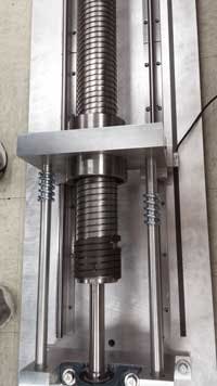
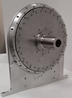
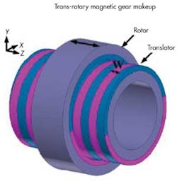
Toliyat’s group has prototyped all three gearing configurations, with the trans-rotary version being the largest scale of the lot. “Applications that capture energy from waves would benefit from the trans-rotary design,” says Texas A&M’s Pakdelian. “To capture reciprocating motion at low speed and high force, your alternatives are hydraulics — which are low efficiency and high maintenance — or, more likely, direct-drive linear machines. These are bulky, costly, and heavy. We can show that trans-rotary magnetics use much less raw material than direct-drive linear machines.”
Pakdelian says the group has built trans-rotary prototypes using magnets about 8 mm wide with a 10-mm pitch. Their prototype using this pitch configuration can convert a linear speed of 1 m/sec to a rotational velocity of 3,000 rpm. “If you want a lower pitch, you have to paste in more magnets. That makes fabrication more difficult in a laboratory setting, but it should be less of a problem if they are assembled on a production line,” says Pakdelian.
The same can be said for radial magnetic gears. “There is no reason why it would be any more challenging to build these than building conventional gearboxes, once you get the process down,” the two explain. Presently, the Texas A&M group is progressing from studying magnetic gear topologies to addressing the practical issues of manufacturing magnetic gears and improving their performance.
Although their prototypes have all been in the subkilowatt range, the Texas A&M researchers think production versions of the radial magnetic gear designs have the potential to work in wind turbines at the megawatt scale without any major manufacturing issues, though, “that is just a theory at this point,” says Johnson.
This file type includes high resolution graphics and schematics when applicable.
About the Author
Leland Teschler
Lee Teschler served as Editor-in-Chief of Machine Design until 2014. He holds a B.S. Engineering from the University of Michigan; a B.S. Electrical Engineering from the University of Michigan; and an MBA from Cleveland State University. Prior to joining Penton, Lee worked as a Communications design engineer for the U.S. Government.
Voice Your Opinion!
To join the conversation, and become an exclusive member of Machine Design, create an account today!

Leaders relevant to this article: