Tips for Smooth, Precise Hydraulic Motion Control
Controlling hydraulic motion with precision involves understanding the fundamental difference between servo motors and hydraulic actuators. Electric motors generally respond linearly to control inputs and can be referred to as “first-order systems.” Simple PI and PID control algorithms can provide precise control of first-order systems, and typical electronic motion controllers or even PLCs implementing simple P, PI, or PID algorithms can easily handle the task.
Some hydraulic systems, on the other hand, must deal with the effects of the compressibility of the hydraulic fluid medium, which can be modeled as a mass between two springs, where the piston and the load are the mass and the oil on either side of the piston is the springs. With such systems, simple P only, PI or PID controls often exhibit performance limitations due to the natural frequency and damping factor of the hydraulic/mechanical design. For such systems, called “second-order systems,” algorithms that employ second derivative gains are often needed.
Placing Poles and Zeros
The technical rationale for these conclusions can be explained using traditional control theory. Control engineers plot poles and zero points on a two-dimensional plane, called the s-plane, according to the behavior of the system’s transfer function (the function representing the relationship between the control outputs of a system to its inputs). In a physical system, poles are caused by devices that store energy. A motor-driven system has one pole in the open-loop velocity-transfer function, because kinetic energy is stored in the motor and load. A hydraulic system has two poles, with one pole corresponding to kinetic energy being stored in the piston, rod, and load and a second pole corresponding to the potential energy of the oil under pressure. Oscillations in hydraulic systems are due to energy being transferred back and forth between kinetic energy and potential energy.
It should be noted that when integrating a velocity-transfer function into a position-transfer function (meaning that both velocity and position of the actuator are being controlled), an extra integrator is added to the open-loop system. And yet another pole is added when using the integrator gain in an electrohydraulic motion controller.
For optimal control, the closed-loop control algorithm implemented by the motion controller should include one gain term for every pole in the closed-loop system. The positions of the closed-loop poles on the plot determine how fast the error between the target and actual motion will approach zero. Providing adequate damping to ensure that the system does not oscillate involves placing poles on the s-plane’s negative axis and as far away from zero as possible. Because of the relative simplicity of the transfer functions that govern PID or PI control, there are limitations in setting the parameter gains to specify where the poles can be safely placed.
If the hydraulic system is relatively stiff, simple PID control may provide adequate system performance and stability. On the other hand, some of the more challenging hydraulic systems are underdamped (i.e., could be prone to oscillations) and it is impossible to control the motion by adjusting PID gains alone, even by applying predictive elements such as feed-forward gains. For these systems, a higher-order derivative gain often needs to be added to provide necessary electronic damping. For control engineers, adding a second-derivative control term to the transfer function allows placing the system poles at any desired location on the s-plane. This enables the engineer to get around any stability and performance limitations due to the system’s hydraulic and mechanical design.
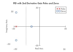
When four gains are used, which correspond to an integrator, proportional, derivative, and second-derivative gain in the control-loop equation, it is possible to place the closed-loop system poles just about anywhere within reason, but the goal is to move them to the left half of the s-plane and keep them close to the negative real axis to minimize oscillations.
Design Challenges
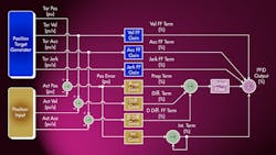
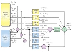
There are some design challenges to overcome when using the second-derivative gain term in the closed-loop algorithm, however. One is the need to have smooth motion profiles where the jerk (i.e., the rate of change of the acceleration) changes smoothly in order to set the value of the jerk feed forward. (Feed forwards are predictive terms that are added to the control-loop equation to help the actual motion profile converge more quickly on the target motion than can be accomplished by the P, I, D, and second-order D terms alone.)
Another design challenge is that some system conditions can make using the double derivative gain problematic. For example, if the feedback lacks precision or there is sampling jitter or noise in the feedback signal, undesired and unpredictable fluctuations in the measured system acceleration can occur. The system designer should select transducers and wire the system so as to minimize these problems.
A third challenge is how to tune a second-order system; there are several ways this can be done. One way is by creating a mathematical model of the system to be controlled and then computing what the controller gains need to be in order to properly control the system.
How do you get the information to use in constructing system models? The more common approach is to create the model from the information available for the different parts in the system and how they are put together. This math-intensive method requires a very experienced control person to accomplish. It usually requires having good specifications for most if not all of the components. The component information is often hard to obtain because manufacturers do not usually supply all the information that is necessary. Therefore, the values of key system parameters are typically not calculated during the system design process. Calculating or estimating a system’s natural frequency and damping factor is complex and can only be estimated empirically.
A much easier way to get a model is to do system identification. This involves exciting the real system (or a simulated one) with a step change in the control signal to the valve and recording how the system responds to the control input. The model constants are modified using trial and error until the model’s response mimics the actual system’s response. There are functions and mathematical techniques that can quickly find the best values for the model in order to minimize the error between the model and the actual system.
Using a Tuning Tool
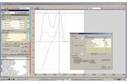
A still easier and more modern way to set the controller gains is to use a motion controller that is supported by an automated system identification and tuning tool provided by the controller manufacturer. An example of this method is to use plots of the motion of the system being tuned to generate a mathematical model of the system. Then, based on the model, the software tool picks a range of appropriate gain combinations for the system. If a certain set of gains is not acceptable (e.g., the system responds too quickly or not quickly enough), the user can adjust the model to calculate a new set of gains.
Conclusion
In short, the second derivative gain allows the limitations due to hydraulic and mechanical design to be overcome. If the hydraulic motion controller being used for a particular application is only capable of implementing a simple PID control algorithm for closed-loop control, the response or bandwidth of the system will be limited by the system’s damping factor and natural frequency.
While increasing the system’s natural frequency can be accomplished by increasing the diameter of the cylinder, this can result in extra costs for a bigger valve and a more capable hydraulic power unit in addition to the extra cost of the cylinder. Increasing the damping factor can be accomplished by adding friction or leakage to the system. Both of these steps increase operating costs and waste energy. It is far more efficient to select a motion controller that can provide second-order control, compensating for most limitations of the physical design.

About the Author
Voice Your Opinion!
To join the conversation, and become an exclusive member of Machine Design, create an account today!

Leaders relevant to this article: