If you run your variable frequency drives at 60 Hz and below, you are not alone. Nearly all the VFDs in North America operate below this nominal frequency threshold. Yet a growing number of high-performance gearmotor systems will benefit from a more aggressive control approach that cranks VFD operating frequencies up to 80, 90, or even 120 Hz.
Under the right circumstances, operating a VFD at these higher-than-usual frequencies can enhance gearmotor performance significantly in the following ways:
- Increasing stability by reducing inertia mismatch
- Widening the available speed range
- Eliminating motor overheating at low speeds
- Enabling the use of smaller motors
Reaping these benefits, however, requires some extra design attention. When you drive motors above 60 Hz, gear ratio and available torque change. And these changes need to be reconciled with the load torques.
What follows are methods for pushing gearmotors beyond 60 Hz, along with justifications for why doing so is a good idea. You will also learn how to break the 60 Hz barrier safely and effectively. Finally, we’ll walk through a common example that will show you how to select the proper gearmotor for a wide speed range.
Breaking The 60 Hz Barrier
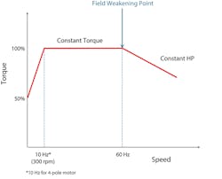
So, what’s the big deal about 60 Hz? In VFDs designed for use in North America, this operating frequency represents the boundary between an induction motor’s constant torque and constant horsepower regions (Fig. 1). Described in terms of the motor’s magnetizing flux, the constant torque region represents the motor’s constant flux region, while the constant horsepower region corresponds to the motor’s field weakened region. Sixty hertz can also be referred to as the motor’s field weakening point.
From 0 to 60 Hz:
- Torque is constant. And it conforms to the torque formula.
Torque (lb-in) = 63,025 * HP / Speed (RPM)
- Voltage-to-frequency ratio is constant, too.
For example: 230 V/30 Hz equals 460 V/60 Hz
Many engineers assume that the inverter and gearmotor must be designed around this 60Hz threshold. And gearmotor suppliers do make it easy to design around this nominal frequency, since most of the catalog and specification data are given for 60 Hz.
However, with a carefully designed drive system and correct ratio, you can push the operating frequency envelope above 60 Hz using either of two proven control methods: field weakening or supercharging. Either method offers the following benefits, which vary depending on the application.
Reduced inertia mismatch. Driving motors above 60 Hz require a larger gear ratio to accommodate the higher input speed. The ratio increase can be up to 100%, depending on operating frequency. This ratio increase can come in handy when you need to reduce the reflected load inertia for better system stability. Stability requires the reflected load inertia to be as close to the motor inertia as possible.
Because load inertias are reflected to the motor shaft by the square of the gear ratio, increasing speed and ratio greatly reduces the reflected load. Doubling the ratio, for instance, would reduce reflected inertia by a factor of four.
Embrace Field Weakening
Field Weakening Point
If you’re convinced that high-frequency VFD operation has benefits in your application, keep in mind there’s more to it than simply dialing up the frequency in the drive controller. Operating above 60 Hz first and foremost requires a thorough understanding of the load and motor torques.
Whenever you operate a drive system above 60 Hz, pay attention to the following effects:
- The voltage-to-frequency relationship is no longer constant. Voltage does not increase, but frequency does.
- Horsepower stays constant.
- Motor torque drops in inverse proportion to the frequency (Fig. 1).
- Breakdown torque drops in an inverse square manner to the frequency. In other words, breakdown torque falls faster than motor torque.
From a design standpoint, this last point bears special attention. When operating beyond the field weakening point, it’s more likely that the application will be limited by breakdown torque.
In most applications, the loss of breakdown torque won’t pose a problem if you adhere to certain limits on operating frequencies. With a smaller motor—typically those under 10 HP—the limit may be as high as 85 Hz.
However, larger motors, which have a sharper drop in breakdown torque, should be limited to 75-80 Hz. Regardless of motor size, it’s also wise to design with a cushion between breakdown torque and load torque. We recommend that breakdown torque be at least 25% higher than the load torque.
Extended Speed Range. Operating above 60 Hz can widen the speed range available from a given gearmotor. Speed range will obviously increase on the top end when you bump up the VFD operating frequency above 60 Hz. However, what may be less obvious is that the speed range will also increase on the bottom end.
Normally, an induction motor running at low speed experiences cooling difficulties when its shaft-mounted fan turns too slowly to dissipate heat. A separately-wired blower can keep it cooler, but a blower increases the motor’s initial and ongoing operating costs. An alternate cooling method involves reducing the amount of torque the motor produces, which in turn lowers the amount of current it draws. Below 300 RPM (10 Hz for 4-pole motor), the torque reduction needed to keep an induction motor sufficiently cool begins to decline linearly to 50% (Fig. 1).
However, driving motors above 60 Hz can eliminate the low-speed cooling issue without the need for expensive blowers or torque limitations. Because field-weakened motors go hand-in-hand with higher gear ratio, gearmotors that deliver the required torque above 60 Hz will inherently have torque to spare below 60 Hz. Consequently, the motor can run slower and cooler below 60 Hz while still meeting torque requirements.
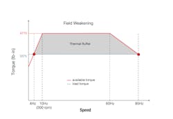
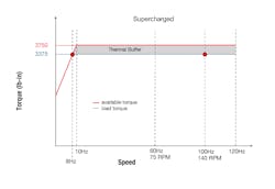
Put differently, gearmotors sized for operation above 60 Hz will gain a thermal buffer—allowing the motor to operate cooler below 60 Hz and to operate below 10 Hz without a blower, which extends the speed range considerably. Constant torque applications easily benefit from this approach. But so do many variable torque applications.
Smaller motors. Yet another benefit of raising the VFD frequency above 60 Hz is that you can sometimes use a smaller motor in a variable torque or supercharged application. The smaller motor occurs because supercharged motors actually have twice the power at 120 Hz than at 60 Hz, which is often surprising to many engineers.
For example, a motor with a 60 Hz nameplate of 1 HP actually becomes 2 HP at 120 Hz. When the application allows the use of a smaller motor, you save money not only on the purchase price of the motor, but also its ongoing operating costs.
Moving Beyond 60 Hz
Despite the benefits of driving motors above 60 Hz, most engineers have never even considered turning up the frequency of their drives. Yet, this unconventional control strategy will improve performance in a wide variety of applications.
Among them are constant torque applications such as conveyors and hoists, as well as variable torque applications such as batch mixers or pumps. Regardless of the application, pushing above 60Hz does require a bit of extra work upfront, but the work will be well worth the effort if you solve your speed, cooling, inertia, or cost problems.
Supercharge the Drive
Supercharged
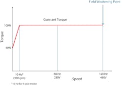
You can take gearmotor performance to a new level through a technique we call supercharging. It entails wiring the motor for 230 V and driving it with a 460 V inverter at twice the motor HP. For example, a 1 HP, 230 V motor is used with a 2 HP, 460 V inverter. So, the motor receives 230 V at 60 Hz, and 460 V at 120 Hz (Fig. 2).
Supercharging works by:
- Shifting the field weakening point upwards. Supercharging extends the motor’s constant voltage-to-frequency relationship and constant torque behavior up to 120 Hz, rather than stopping at 60 Hz.
- Forestalling the drop-in breakdown torque. The loss of breakdown torque that would normally begin at 60 Hz won’t take place until 120 Hz. In essence, supercharging eliminates the worry about not having sufficient breakdown torque.
Supercharged gearmotors do have a noteworthy limitation related to increased thermal losses in the gearbox, due to a higher input speed. These losses warrant a careful evaluation of the gearbox’s thermal capacity. However, these churning losses will be offset to some degree by the increased cooling from the motor’s fan, which spins faster in a supercharged system.
In practice, the gearbox losses can sometimes prevent supercharged systems from reaching the full 120 Hz. A conservative rule-of-thumb for evaluating supercharging is that applications below 25,000 lb-in or applications with gearbox ratios higher than 25:1 should have adequate thermal capacity. Outside of those guidelines, high temperature seals (FKM) and synthetic oil can be used to increase the thermal capacity. When in doubt about thermal capacity, check with the gearmotor manufacture.
Running the Numbers
Here’s a typical conveyor application with a constant load. The application requires a speed range of 12:1.
Load = 5 HP, RPM = 11.5 to 140
Running the Numbers Method 1: 60 Hz Maximum
Without field weakening, the maximum frequency is set to 60 Hz.
And from Fig. 1, the lowest speed the motor can safely operate without a blower is 300 RPM. So, to determine the corresponding frequency of a 4-pole motor, use the Hz formula:
- Hz = RPM * # of poles/120
- Hz = 300 * 4/120 = 10
The acceptable speed range for the gearmotor is 10-60 Hz, which is only 6:1 and not sufficient for the required application. Therefore, an auxiliary blower fan is required to operate below 10 Hz.
Running the Numbers Method 2: Field Weakening
Looking at the manufacturer’s breakdown torque for 5 HP, it is acceptable to assign the highest speed to 85 Hz.
Step 1: Determine Load Torque
Always use the highest speed in the torque formula for a constant torque application. Therefore,
- TLoad = 63,025 * HP/RPMHighest
- TLoad = 63,025 * 5/140 = 2,250 lb-in
Step 2: Determine RPM at 60 Hz
Since the highest speed is set at 85Hz, calculate the 60 Hz speed.
- [85/125] = [60/X]
- X = 88
So, select a 5 HP, 88 RPM from a 60 Hz catalog.
Step 3: Determine Available Torque at 10-60 Hz
The available torque at 10-60 Hz is higher than the load torque, which is necessary to provide the thermal buffer. Using the torque formula and the 60 Hz speed:
- TAvail = 63,025 * HP/RPM60 Hz
- TAvail = 63,025 * 5/88 = 3,580 lb-in
Step 4: Determine Low Speed
Determine the motor’s lowest permissible speed. Since the point falls on the slope below 0 and 300 RPM, use SEW’s Low Speed Formula.
- RPM = [600 * TLoad/TAvail ] – 300
- RPM = [600 * 2,250/3,580] – 300 = 77
From the Hz formula,
- Hz = 77 * 4 / 120 = 2.6
Thus, the permissible speed range is 2.6-85 Hz (32:1), which is more than adequate. Repeating the calculations in steps 2-4 for other frequencies above 60 Hz yields the results below. All but the first row are acceptable options, since their speed range is at least 12:1. But, the solution with the maximum thermal buffer and thus the largest speed range is 2.6-85 Hz.
Field Weakening Method
Running the Numbers Method 3: Supercharging
When supercharging, there is no reduction in torque above 60 Hz. Instead, there is constant torque from 10-120 Hz. However, depending on the VFD, size of gear reducer, or other reasons, it may not be desirable to go all the way to 120 Hz.
Step 1: Determine Hz Range
Select the speed range depending on maximum Hz. In this example, 100 Hz is the desired maximum. 10-100 Hz is constant torque, but it is only 10:1. To achieve 12:1 range, calculate the low Hz.
- 100 / 12 = 8Hz
Therefore, 8-100Hz is needed. But, a thermal buffer must exist to avoid using a ventilator fan at 8 Hz. Perform the next steps to determine if 8 Hz is permissible.
Step 2: Determine RPM at 60 Hz
Since the highest speed (125 RPM) is assigned to 100 Hz, calculate the 60 Hz speed.
- [100/125] = [60/X]
- X = 75. Therefore,
- Gear ratio = [1750/75] = 23.3
Step 3: Determine HP at 60 Hz
From 10-100 Hz, the torque is constant, but the HP varies proportionally. Rearrange the torque formula to calculate the required HP at 60 Hz.
- HP60 = [ TLoad × RPM60 ]/63,025
- HP60 = [2250 × 75]/63,025 = 2.67 HP
Use a nominal 3 HP motor. Since it is larger than 2.67, it provides a buffer which may be sufficient to allow operation as low as 8 Hz. Notice that it is also smaller than the 5 HP motor used in Method 2.
Step 4: Determine Available Torque at 60 Hz
Use the torque formula to calculate the torque available from the 3 HP motor.
- TAvail = 63,025 * HP/RPM60
- TAvail = 63,025 * 3/75 = 2,520 lb-in
Step 5: Determine Lowest Speed
Determine the motor’s lowest permissible speed. Since the point falls on the slope below 0 and 300 RPM, use SEW’s Low Speed Formula.
- RPM = [600 * TLoad/TAvail ] – 300
- RPM = [600 * 2,250/2,520] – 300 = 235
From the Hz formula,
- Hz = 235 * 4/120 = 7.8
Therefore, 8-100 Hz speed range is permissible with 3 HP, as shown in Fig. 4.
Supercharging Method
Running the Numbers
Field-weakening provides a thermal buffer that allows the motor to operate at a lower speed without a blower. However, the highest frequency is limited due to reduction in breakdown torque.
Supercharging allows frequencies up to 120 Hz without affecting the breakdown torque. It also yields a higher ratio (i.e., a lower reflected load inertia) and a smaller motor, as summarized in Table 2 and Fig. 4 above.
