Axial-Flux Motors and Generators Shrink Size, Weight
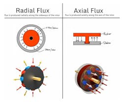
Today, most electric machines operate with radial flux (RF). Magnax offers a new concept, though—a machine that operates with axial flux (AF). Figure 1 provides a comparison of the RF and AF technologies.
1. Comparison of radial- and axial-flux machines.
Magnax says the key to the high power density is its motors’ yokeless AF design with two rotors at each side of the machine. The yokeless AF motors have a shorter flux path, and permanent magnets are farther away from the axis, resulting in greater efficiency and leverage around the central axis.
Furthermore, thanks to the axial flux design, very little copper is wasted on overhanging loops on the windings. The motors have zero overhang; that is, 100% of the windings are active.
The technology is scalable from small motors (i.e., electric vehicles) to large generators (i.e., wind-turbine generators).
According to the company, a 100-kW axial-flux permanent-magnet (AFPM) generator for a mid-size wind turbine offers the following benefits:
- Increased efficiency (+96% efficiency, up to 97% for larger generators).
- Reduced length (5X to 8X shorter than traditional wind-turbine drive trains).
- Reduced mass (2X to 5X lighter than geared or traditional geared direct-drive generators).
- Reduced resources requirement (½ to ⅓ of materials required vs. traditional RF direct-drive geneators, which also results in lower costs).
Design features of the Magnax axial-flux machine include:
- Dual permanent-magnet rotors, for the highest possible torque-to-weight ratio.
- Yokeless stator, for the shortest possible flux paths.
- Rectangular cross-section copper wire, for 90% possible copper fill factor.
- Concentrated windings, for the lowest possible copper losses (no coil overhangs).
- High-performance grain-oriented electrical steel (ThyssenKrupp GOES), lowering the core losses by as much as 85%.
- A patented system for cooling the windings, for the lowest possible stator temperatures.
- The entire manufacturing chain is based on low-cost, easy-to-scale production processes.
AFPM machines perform well at a very broad range of rotational speeds, which makes them suitable for high-speed-low-torque and low-speed-high-torque applications.
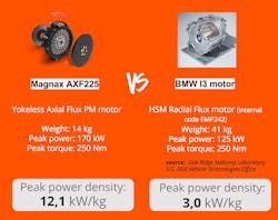
2. Here’s a comparison of the BMW I3 motor and the Magnax AXF225.
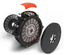
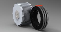
AF machines are more compact because they’re much more effective from an electromagnetic perspective than RF machines, which is often crucial for built-in applications, such as in vehicles. The slim and lightweight structure results in a machine with a higher power and torque density. A good example is the comparison of the BMW I3 motor, which has a weight of 41 kg for 125-kW peak power vs. the Magnax AXF225, which has a weight of 14 kg for a peak power of 170 kW (Fig. 2). Plus, according to the company, AFPM machines can provide the highest energy efficiency of all electrical machines, mainly because there’s no yoke and the flux paths (through the grain-oriented electrical steel cores) are very short. Figure 3 shows a Magnax 275-mm AFPM motor.
3. Magnax’s 275-mm AF motor targets e-mobility applications.
Moving Past Induction Motors and Gearboxes
Electric machine solutions are currently dominated by combinations of standard induction motors and gearboxes. These induction motors have a typical maximum efficiency below 90% at full load, and lower at partial loads. They also often produce long, massive drive trains.
Newer machine concepts use permanent magnets to generate a constant magnetic field and thus generate a flux by design. As a result, the power density and dynamic performance of PM machines is higher than induction or electrically excited machines, where the magnetic field must be created (directly or indirectly) via an electrical current.
Radial-flux (RF) direct-drive (DD) machines are an alternative solution to overcome the efficiency and reliability issues of traditional solutions associated primarily with gearboxes. DD machines eliminate the gearbox and connect the generator or motor coupled directly to the load. For this solution to be effective, the motor/generator must be able to supply the required drive torque directly, and at low speed, which requires an entirely new motor/generator design.
RF DD machines are heavier and more expensive due to the use of radial magnetic flux to transfer power. Fundamental electromagnetic and thermal constraints with this approach result in machines that are often both wide and long, compared with state-of-the-art models.
Large machines also require rare-earth permanent magnets and copper for the coils. (According to to Öko-institut e.V, RF DD generators require 600- to 700-kg magnet material per megawatt.) The use of rare and valuable resources has a big impact on the cost and lifecycle analysis of RF DD machines. Figure 4 compares a 300-kW RF DD generator and a 3x100-kW Magnax AF DD generator (total = 300 kW).
4. Comparison of a 300-kW radial-flux direct-drive generator (left) and a 3x100-kW Magnax AF DD generator (right).
Axial-Flux Direct-Drive Machines
A fundamentally different approach to direct drive is to put two sets of magnets parallel to each other, perpendicular to the axis of rotation. This axial-flux topology provides machines that are less wide and heavy than RF DD machines. As well as being more compact, AF DD machines can reach higher efficiencies than their RF DD counterparts. Axial Flux machines have much higher power density because:
- AF machine magnets are located further away from the central axis, resulting in a larger "lever" on the central axis.
- AF machines have an inherently more efficient electromagnetic topology. In RF machines, the magnetic flux moves through the first tooth and then via the stator back to the next tooth to the magnets. In contrast, the flux path for AF machines is shorter—from the first magnet, through one core, and straight onto the other magnet. (only applicable for dual-rotor topologies such as Magnax machines). In a wind-turbine application, for instance, we need less than 300 kg of magnet material per megawatt instead of 600-700 kg per megawatt for RF DD generators.
In addition, the flux in RF machines must make a “bend” and follow a two-dimensional path. Therefore, radial flux machines can’t use oriented electrical steel for the cores (stator). In the case of AF machines, the flux path is one-dimensional, so Magnax can use grain-oriented steel for its axial flux machines. This results in fewer iron losses when the flux passes the cores. Oriented steel makes it easier for the flux to pass, which results in an additional efficiency gain.
- For RF machines, as much as 50% of the windings aren’t active (the part located at the exterior of the stator teeth that’s only used to make loops, or so-called “coil overhang”). The coil overhang adds electrical resistance and heat dissipation and has no function. It’s what they call a “distributed winding” and results in much worse overall power/weight ratio compared to axial-flux machines, which have no coil overhang. For Magnax AF machines, 100% of the winding is active.
- In RF machines, heat must be transported through the stator to the outside of the machine. And, steel isn’t a good heat conductor. Coil overhang is also difficult to cool because it’s not directly in contact with the motor casing. The AF machines allow for optimal cooling because the windings are directly in contact with the exterior aluminum outside casing. Because aluminum conducts heat very well, the windings of the AF machines stay cool while the resistance of the copper remains low, resulting in a higher efficiency.
Scaling the Machine Concept
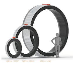
The Magnax concept is scalable from 150 mm diameter to 5400 mm diameter or more. This multi-stator “feature,” where multiple machine discs are combined in parallel, adds flexibility by multiplying both torque and power (Fig. 5).
5. Maximum flexibility and scalability is achieved while maintaining high manufacturability.
Historically, AF designs were confronted with design and production challenges:
Mechanical: The high magnetic forces acting between the rotor and the stator produce an engineering and material challenge in maintaining a high-tolerance uniform air gap between these two components. Magnax solved this by improving the design.
Thermal: Windings in an AF machine are located deep within the stator and between the two rotor discs, which presents a greater challenge in terms of cooling than for an RF DD design. Magnax solved and patented a new concept where aluminum pieces surround the cores and extract the heat directly to the outside of the machine. As a result, there’s no need to push fluids through the cores (which can generate local turbulences and air bubbles, and lower structural strength). On the outside, cooling is accomplished via cooling fins or by installing a water jacket.
Manufacturing: AF machines have thus far been very difficult to manufacture because the stator iron’s design has continued to be based on that of an RF machine, using a stator yoke to close the flux loop. Magnetic forces between the rotor and stator discs tend to make it very difficult to keep the air gap between them uniform. If they start to wobble or bend, the discs can start rubbing against one another, leading to bearing damage at best, and rapid, spectacular unscheduled disassembly at worst.
Magnax’s solution was first to remove the iron yoke from the stator, but keep the iron teeth. Then, there are two rotor discs with the stator between the discs. A small air gap exists between rotors and stator, which contains the windings, while the rotors contain the magnets. The two rotor discs exert an equal (but opposite) attraction force on the rotor.
The discs, however, are directly connected to each other via the shaft ring, so the forces cancel each other out. The internal bearing doesn’t carry these forces; it only needs to keep the stator in the middle between the two rotor discs. Theoretically, when the stator is exactly in the middle, it’s in equilibrium and no forces act upon the bearing, although there’s always a small force that acts on the internal bearing.
Flux Efficiency
The Magnax Axial Flux machines use ThyssenKrupp’s high-performance grain-oriented electrical steel (GOES) for its cores. Grain-oriented steel can’t be used with RF machines because the flux paths in these machines follow a nonlinear 2D path. In the Magnax AF topology, the grains of the steel are oriented in the same direction as the flux paths. Low losses and excellent permeability of the grain-oriented material in the rolling (axial) direction results in a machine with 85% reduced stator core losses and a slight increase of the electromagnetic torque.
Because the length of the machine is very short (140 mm for a 1600-mm outer diameter generator, for example), multiple machines (discs) can work in parallel, which is called multi-stator topology. This is usually done when the outside diameter of the generator or motor assembly must be kept limited.
Combining multiple machines in one stack gives a lot of flexibility to the end-user application and enables a more “standardized” engineering approach. This configuration allows for fault tolerance, as the machine can keep working even if any of the stages is damaged or disconnected.
To reduce the axial length and weight even more, back-to-back rotors can be combined into one, while internal bearings can be replaced by one or two external bearings.
High-Speed Motor Applications
Magnax’s AF concept is used for electric-motor applications for e-mobility, where weight and size must be kept to an absolute minimum while delivering high amount of power and torque. Because torque directly relates to diameter, the diameter is the main specification for machine size. Small versions of the company’s yokeless AF motors are usually water-cooled and reach power densities up to 15 kW/kg, which is twice as high as current best-in-class motors.
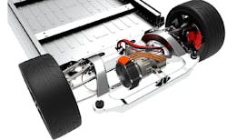
In transportation systems, motor weight is critical and must be minimized. The AF motors are used for drive-train applications with power densities up to 15 kW/kg. The peak efficiency of these machines can reach 98% and remains very high at partial loads. Figure 6 shows a Magnax motor installed in an automobile.
6. The AXF275, which delivers 300-kW with a weight of only 26.5 kg, is integrated into a car chassis.
AF motors can be combined with gearboxes in different powertrain configurations, chassis-mounted or in-wheel. Some e-mobility applications require direct-drive motor concepts. A gearless design significantly reduces complexity and maintenance requirements. These motors already deliver the nominal torque at 0 rpm and have a very compact design, so they’re well-suited for direct-drive (in-wheel) configurations. For such applications, they ensure that the efficiency mapping is optimized for lower rpm ranges (usually a wheel speed of 500-2,000 rpm). Outrunner configurations are possible to reduce the weight even more.
The large version of Magnax’s machines (AF direct-drive generators) are suited for wind turbines:
- Wind turbines with induction motors and gearboxes are generally less efficient (below 90%, while the AF generators can reach 96% or more). Also, gearboxes are considered to be more maintenance-intensive and less reliable due to the higher amount of moving components.
- Traditional direct-drive generators (typically based on RF topology) are two to five times heavier than the AF generators and a few percent less efficient compared with AF direct-drive generators, according to the company. Efficiency is improved because grain-oriented steel cores are used in combination with shorter flux paths, and windings have a higher copper-fill factor.
Applied Power
Magnax recommends 750 V from the battery with an inverter. The company expects that voltages will increase even more in the future, which will further reduce the current.
A 400-V ac motor or lower (like 100 V for motorbikes) supplied by Magnax can serve as an alternative for lower-powered motors, which doesn’t change much on the machine specs. Of course, the lower the voltage, the more difficult it becomes to find an inverter that can cope with the high current.
Daan Moreels is Co-founder of Magnax.
Reference:
White Paper: High Efficiency Axial Flux Machines, Daan Moreels, Peter Leijnen, May 2018.
