Advances in Variable Speed Drives Ease Complications
Download this article as a .PDF
Variable speed drives (VSDs), sometimes also known as variable frequency drives, are electronic devices used to regulate the speed of an ac induction motor. Electric motors consume approximately 25% of the world’s electricity for industrial and consumer applications. The key benefit is to provide new and improved process control, while also boosting power factor and overall system efficiency (energy savings). VSDs are used in a multitude of applications, ranging from relatively simple applications (like pumps and fans) to more complicated applications (e.g., winders and dynamometers).
The Basics of Conventional Drives
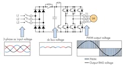
VSDs help operators to control the motor at any command speed. They provide energy savings and regulation capabilities while extending the life of equipment. VSDs are non-linear electrical loads, meaning that the input current waveform does not follow the sinusoidal waveform as the supply voltage. To establish a direct current (dc) bus voltage level and charge the capacitors, VSDs typically rectify the incoming alternating current (ac) voltage.
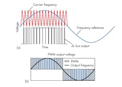
Two internal waveforms are produced: the carrier and the output. The carrier waveform is typically around 8 kHz to 15 kHz and is a triangle-shaped waveform at a much higher frequency used to drive the motor. The output waveform is a simulated sine wave at the desired motor speed’s frequency. Conventional drives operate by converting ac to dc and then back to ac. Conventional drives convert ac to dc using diodes. Diodes only conduct when the voltage at the anode (ac side) is greater than the cathode (dc side).
However, the dc supply (dc bus) generated from diode rectification is not uniform because only the peaks of the ac input voltages is higher than the dcc supply. Thus, a dc bus ripple from the electric conversion process occurs. Conventional drives use large amounts of electrolytic capacitors to smooth out the dc bus ripple.
Once a stable dc bus is generated, the drive can utilize the smoothed dc bus voltage to generate an output voltage waveform to control a motor at the requested voltage and frequency. Outputted dc pulses in a waveform known as pulse width modulation (PWM) generate the voltage.
Conventional Drive Pulsing
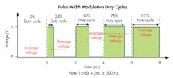
PWM waveforms, as the name indicates, are generated using pulses of varying thicknesses (widths). For a conventional drive, each pulse is generated by turning on and off an insulated gate bipolar transistor (IGBTs) that allows the dc bus voltage to reach the motor. Therefore, each pulse resembles a square wave.
The time the dc bus is supplied to the motor compared to the overall total time period equates to the average voltage for a specified segment of time. The VSD varies the time and width of the pulses, providing the correct frequencies to the drive motor at the required speed for the load. The dc bus charge is drawn down due to the motor consuming energy which is then replenished by the rectified incoming ac voltage.
One method of determining when and for how long the drive needs to generate a pulse is referred to as sine-triangle pulse width modulation. The technique requires a reference voltage waveform (waveform needed to operate the motor) and a waveform that determines the sample rate (in this case, a triangular wave set to the frequency of the drive’s carrier frequency). The PWM technique has the sampling waveform overlaid on top of the reference waveform. The drive’s IGBTs turn ON and stay on whenever the reference voltage waveform is greater than the triangular carrier frequency waveform (i.e., Blue > Red = ON).
The RMS output voltage of these pulses determines the voltage being sent to the motor. The period of positive and negative pulses determines the fundamental frequency of the waveform. The impedance of the motor, allowing it to react to the PWM voltage as if it were purely sinusoidal, filters the pulses. The resulting sinusoidal current waveform is a direct indication that the motor is reacting to only the fundamental voltage (RMS voltage) of the PWM waveform. The dc bus draws the replenishment current at the peaks of the rectified sine wave which may cause problem with current harmonics.
Harmonic currents occur on multiples of the fundamental frequencies. Typically that is 60 Hz for the United States. Harmonics can cause cables to overheat, tripped circuit breakers, and stress for transformers upstream. They can impact clean power delivery which results in voltage distortion and equipment disruption.
Advancements in Variable Speed Drives
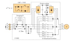
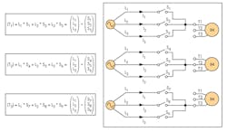
A matrix is a mathematical principal used to describe an arrangement of symbols, expressions, and/or numbers into rows and columns. The intent is to take a very complicated array of actions and describe and implement these actions in a clear and concise manner. A variable speed drive that uses a matrix arrangement can be described as using nine bi-directional IGBTs in three sets of matrices. Each matrix describes the connection between the input power and one output phase.
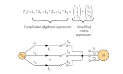
The figure below is a representation of the mathematical and simplified electrical equivalent of one matrix set. A matrix drive uses fast acting switches (i.e., the IGBTs) configured in a matrix to generate an ac output voltage directly from three-phase ac input power. The supply voltage is outputted to motor by closing one of the three bi-directional IGBTs. Therefore, no more than one IGBT can be turned ON at same time to prevent shorting the input power supply.
As is shown below, a potentially complicated expression can be presented in a simpler manner. Again, each of the above matrices represents a connection to one output phase. Therefore, there are three sets of matrices, one for each output phase.
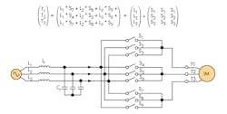
Since the power source is identical to all three matrices, each input phase can be connected at a common point to simplify the overall circuit. Each motor phase has independent access to the line. Turning on and off one of its switches will dictate what voltage is sent to each motor phase. Depicted below is the final configuration. A LC input line filter is added before the IGBTs to turn the regenerative waveform into a clean sine wave.
Matrix Drive Pulsing
A VSD using a matrix arrangement technique generates its output voltage waveform nearly identical to that of a conventional drive. The only difference lies with how the matrix drive generates its output pulses. It has no dc bus smoothing capacitors, and thus no dc bus to generate pulses for its PWM waveform. Instead, ac voltage is directly applied to the motor to generate its PWM waveform pulses using bi-directional IGBTs.
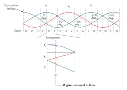
At any given moment in time the matrix drive has access to any input phase. Each of these voltages presents a different voltage potential that can be sent to any motor phase. Therefore, the drive has the ability to send three distinct line-to-line voltages to any two phases at any given time.
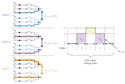
To generate a pulse equivalent to that of a conventional drive’s dc bus, the matrix drive would need to send pulses with the potential of Vr-t above. However, the matrix drive has access to two additional pulses. Therefore, instead of outputting Vr and Vt across two phases, the matrix drive takes two steps in generating each pulse. The first step is to add Vs-t and Vr-s, which equals Vr-t. Therefore, each individual pulse would be accomplished by using three distinct switching patterns to generate the full pulse. The pattern creates a three level output pulse.
Generating a Waveform
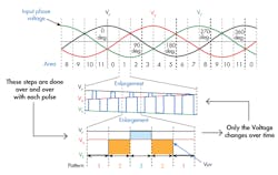
The VSD matrix drive implements the steps above continuously as the input voltage changes. The only difference in the pulse pattern is the level being pulsed to the motor. As you see below, for the same period of time the minimum and maximum voltages do not change. The mid voltage (Vr) does change, thus providing a pulses output using a variable three-level control.
The matrix drive generates an output waveform from resulting current draw. Unlike other low-input harmonic current solutions, the matrix drive does not force current into the drive to reduce harmonics. The matrix drive draws current with low harmonic content naturally. Each time the drive generates a pulse to the motor using the input voltage, a corresponding current draw occurs.
The current draw is taking from the line during each step of the generation of the variable three-level output. The result of generating a full PWM output voltage waveform to control the motor naturally results in an input current waveform that is sinusoidal with low harmonic currents. The matrix drive can operate at rated power with less than 5% total harmonic distortion at the input of the drive with near unit power factor (0.98 or better).
Comparing Variable Speed Drives
While conventional drives can experience harmonics, there are ways to mitigate them. These include active front-ends and multi-purse transformers. This requires additional components to operate with the conventional VSD. Obviously there are downsides to this method due to cost increases, the wiring required, and extra space requirements.
A VSD with a matrix design accomplish low harmonics within itself. The downside is that VSD matrix drives have a higher initial cost than conventional VSDs. VSD matrix drives are suitable for several applications that use conventional VSDs, including centrifuges, conveyors, escalators, fans, feeders, metal working equipment, mixers, pumps, and steel grinders.
