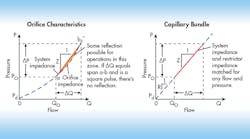
Pressure transients in hydraulic systems are usually caused by valve operations that then create pump ripple and water-hammer effects. All of these can lead to pipeline failures, reduced operating efficiencies, noise, and vibrations. Solving this problem often involves expensive active elements such as relief valves, rupture discs, and controls valves, or else passive-but-complicated devices such as surge tanks and accumulators. A simpler, passive method of controlling transients can be accomplished using line restrictors. They are often effective for damping pressure transients in systems with long fluid lines.
Sizing these restrictors takes a certain amount of care and experience. But the task can be simplified by using a method of matching impedances—a technique common in electrical, acoustic, and mechanical systems, but not widely applied to hydraulics.
In the matched impedance methods, the flow restrictor is installed in a line so that pressure pulses arriving at the restrictor do not get reflected back down the pipe. This is done by sizing the restrictor to the physical characteristics of the flow system and the fluid properties. Transients are typically simple step increases in pressure that pass through a steadily flowing system. They generate an increased volumetric flow rate computed from basic water-hammer analysis:
ΔQ = A(ΔP/ρα)
where ΔQ is the change in flow (m3/sec); A is the cross-sectional area of the pipe (m2); ΔP if the pressure change (Pa); ρ is the fluid’s mass density (N-sec2/m4); and α is the wave propagation velocity (m/sec).
When the pressure pulse and its concurrent flow pulse hits the flow restrictor, the pulse is reflected unless the restrictor passes exactly the same ΔQ for the arriving ΔP wave. In severe cases of deflection, the pressure pulse can nearly double in magnitude. Reflections can be so severe that they cause local cavitation in the lines and near the ports of hydraulic components and cause damage. The object of transient control, therefore, is to make the pulse leave the line via the restrictor with no reflection.
Two types of flow restrictors can be used to damp pressure transients: an orifice plate and a bundle of capillary tubes. The design of these elements depends primarily on the fluid and line characteristics. For orifice restrictors, the relationship between pressure and flow is:
Q = KAo(2(P − Pd)/ρ)0.5
where K 1s the constant Cd/(1 − β4), Cd is the discharge coefficient, and β is the ratio of orifice to pipe diameters; and Pd is downstream pressure (Pa).
From a consideration of steady-state flow conditions, the two equations can be arranged as:
KAo = (ρ(2Qo + ΔQ)/2Z)0.5
where QO is the steady-state flow rate (m3/sec); and Z is the characteristic system impedance (N − sec2/m4) which is equal to ρα/A.
This equation defines the orifice size needed to prevent reflections for a specific pressure and flow change.
Typically, one orifice can absorb or damp only one specific pressure pulse level, limiting the practicality f orifice restrictors. Normally, they are used in pairs—one at each end of a pipeline—to damp transients in the system operating at two clearly defined flow rates.
A capillary = bundle restrictor is characterized by a linear relationship between flow rate and pressure change:
ΔP = RΔQ = 128γLρΔQ/πND4
where R is he capillary tube-bundle flow resistance (N-sec/m5); L is the length of the tube bundle (m): γ is the kinematic viscosity (m2/sec); N is the number of capillary tubes in the bundle; and D is the diameter of the capillary tubes (m).
This equation assumes the inertial effects during unsteady flow in the tube bundle are unimportant, and it neglects entry-length effects. That is, it assumes the existence of steady, fully developed laminar flow.
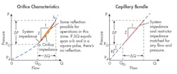
Comparing the first equation to the last one gives the condition that R = Z for zero reflections, which implies the results are independent of flow variables. Thus, a capillary restrictor is sized only for fluid and pipe characteristics and is not affected by pressure level or flow. As result, capillary restrictors are more universally applicable than orifices, although they may cause large pressure drops at high flow rates.


