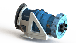
Gearboxes in wind turbines, more than those in any other application, tend to fail prematurely. In fact, at some wind projects, up to half of all gearboxes fail within a few years. There are several reasons for this, including the relative newness of the industry, the rapid evolution of turbines to extra-large sizes, poor understanding of turbine loads, and an emerging (and largely unexplained) failure mode in turbine bearings called axial cracking.
Wind-industry progress
The target service life of the typical wind turbine is usually about 100 million main-shaft revolutions over 20 years, but most turbines never survive that long without problems. So to boost reliability, turbine manufacturers are working to understand and address the causes of premature failures. The effort is paying off. Data collected by government labs such as the National Renewable Energy Laboratory, part of the U.S. Dept. of Energy, Golden, Colo., and Sandia National Laboratories, Albuquerque, confirm gearbox reliability is steadily improving.
Consider how several past approaches to designing wind-turbine gearboxes — the weak link often responsible for failures — are yielding to better approaches.
Past: Full-scale testing of wind-turbine gearboxes was expensive if not impossible, so OEMs could only validate designs with a few short tests, mostly on subcomponents.
Now: Large test stands, which have proliferated in recent years, let engineers test their gearboxes more rigorously.
Past: Until recently there was a basic misunderstanding about how wind-turbine gearboxes respond to loads to which they’re subjected, partly because legacy and nonspecialized modeling software tends to underestimate the effect of these loads on gear and bearing stresses.
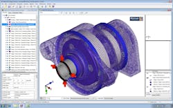
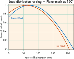
Now: Today’s design tools and software such as RomaxWind, by Romax Technology Inc., with U.S. headquarters in Troy, Mich., help engineers accurately predict stresses in wind-turbine gears and bearings. Turbine-specific RomaxWind lets engineers pinpoint existing gearbox problems — a major source of problems — and design heartier wind turbines.
Past: Engineers stuck to one kind of drivetrain, those with high-speed gearboxes. These have the lowest upfront cost because they let engineers fit the turbine with a small generator. However, high-speed gearboxes fail more than other options.
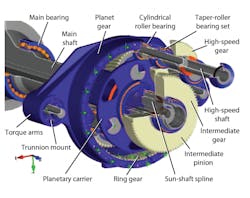
Now: Some engineers, armed with data they derived from RomaxWind and other software, now design turbines with medium-speed gearboxes that have fewer stages than high-speed types — two rather than three. These have fewer gears and bearings, so they are inherently more reliable. They’re also more reliable, yet more costly, than traditional high-speed options but far less costly than direct drives. The latter needs little maintenance but has higher upfront costs.
Many wind-turbine OEMs now think medium-speed drivetrains offer the best balance between upfront and operations costs — for the lowest overall cost of energy. That’s significant because the Holy Grail for turbine engineers is to make wind energy cost competitive with fossil-fuel sources.
Past: Sometimes gear manufacturers missed the demanding quality mark for wind-turbine gearing.
Now: Recent changes in manufacturing aim to reduce quality-related failures, though this is one area where there’s room for improvement. Case in point: Many gearbox failures result from grind tempering, an overheating of gears during grinding caused by incorrect grinding parameters or inadequate coolant. When the temperature rises above the gear material’s tempering temperature during grinding, it reduces the gear’s hardness and strength. But most turbine OEMs today require that suppliers check gears for the presence of grind temper. Through a process known as nital etching, a lab cleans the gears and applies nitric acid solution to highlight differences in microstructure. Tempered areas on the gear appear darker than undamaged areas.
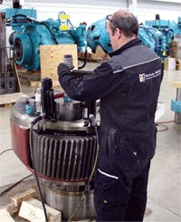
Likewise, gearbox failures caused by insufficient material cleanliness during manufacture are still common. Usually, it’s the presence of a foreign particle or inclusion in a gear that induces a localized area of higher stress. If the inclusion is large and close to an active contact surface of the gear tooth, the gear will fail prematurely. But newer nondestructive tests such as phased-array ultrasonic testing are reducing the number of gear failures caused by inclusions.
Persistent problem: Axial cracking
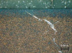
Despite all the recent improvements, one major cause of gearbox-bearing failures is axial cracking, sometimes called white-etch cracking for the irregular white areas that appear when affected bearing surfaces are chemically etched and examined under micrographs. Axial bearing cracking consists of lengthwise cracks on the bearing’s inner ring along the roller path. The cracks form in gearboxes from all manufacturers and on turbines in disparate installations. For reasons that remain unclear, axial-cracking failures usually arise in bearings that support gears of the intermediate and high-speed stages. Cylindrical-roller bearings are more vulnerable than other types, while tapered-roller bearings are less so.
Established guidelines don't apply here. As mentioned, bearings in wind-turbine gearboxes are designed to last 20 years. To meet this target, most manufacturers follow Germanischer Lloyd guidelines for analyzing gearbox bearings. They were established by the international engineering and design-certification body DNV GL Group, Oslo, Norway. DNV-GL technical certifications guide the design of large-scale energy installations, including wind turbines and onshore and offshore wind farms.
Among other design requirements, DNV-GL guidelines require that wind-turbine suppliers analyze gearbox bearings for rolling-contact fatigue using established methods. When engineers follow these guidelines, calculated odds of failure over the turbine life is 10% or lower, and calculated life can reach 175,000 hr, depending on the analysis method. In fact, most engineers select bearings that exceed these minimum criteria.
The problem is that these calculations only consider failures from rolling-contact fatigue — a cumulative bearing fatigue that develops at predicable rates. Here, odds of failure depend on how the bearing’s subcomponents are heat treated, how the surfaces are finished, how cleanly the steel is manufactured, and what kind of steel alloy they are made from.
In contrast, axial-cracking failures have only been observed for the last 20 or so years in just a few industries, so they aren't fully understood, so GL calculations don't factor for their effects. But axial-cracking failures are common. They happen at stress levels much lower than those that cause rolling-contact fatigue. Plus, they typically happen within the first couple years of turbine operation.
Axial-cracking failures usually take place in a bearing’s inner ring because the bearing’s inner-ring diameter is smaller than its outer-ring diameter. Thus, the inner ring sees more contact stress for a given load. What's more, inner rings are usually smaller than the shafts on which they mount. During assembly, the manufacturer heats the rings to make them expand and slides them onto the shafts. When the rings cool, they contract into an interference fit with the shaft that helps them stay securely in place.But this creates a tensile hoop stress on the ring, which superimposes on the contact stress in the bearing ring during normal operation. The compounded stresses accelerate the accumulation of fatigue damage.
Though there’s no universal consensus, most engineers in the industry believe axial cracks originate in the subsurface of the bearing ring where orthogonal shear stress is highest. Then they propagate to the surface. At first, compressive residual stress at the bearing surface holds emerging cracks closed. But bearing rollers riding over the crack make spalls, which slowly grow until they cover the surface of the inner-ring roller path, ultimately rendering the bearing nonfunctional.
While the exact causes are still being explored, ongoing experiments and practical knowledge gained by engineers in the industry suggest some steps that can reduce the odds a bearing will fail due to axial cracking.
1. Use bearings with case-carburized inner rings and optimal levels of retained austenite.
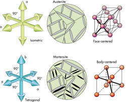
Case-carburized bearings have much higher fracture toughness than through-hardened bearings. That toughness reduces axial cracking. Here’s why: The case-carburized layer consists primarily of two phases of steel, martensite and austenite. The correct proportion of these two steel phases boosts resistance to axial-crack failures. Martensite is the harder of the two phases and gives the case its high strength. Austenite is softer than martensite, but is more ductile and resistant to crack initiation, thus providing better fracture toughness. Bearings with retained austenite levels greater than 20% by volume do not develop axial cracks.
Even so, the optimal upper limit on retained austenite isn’t established. That’s because there are two complex factors that affect the upper limit on it. One is the previously mentioned effect on surface hardness. The other is more subtle.
When austenite is exposed to high mechanical stresses, such as those in a bearing, some of it transforms into martensite. Differences in the crystalline structure between the two forms of steel increase the new martensites volume. The change in volume alters the shape of the bearing’s roller path, a part carefully engineered to minimize stress, but only in its original shape. The volumetric increase also raises tensile residual stress in the bearing, which shortens fatigue life.
2. Use bearings with black-oxide coating.
Some designers think black-oxide coating helps bearings resist axial cracking. For years, the coating has improved bearing-surface break-in and protected against corrosion, and this surface protection may defend against axial-crack failures as well. But the exact mechanism for the improved resistance isn’t known. Some suspect it’s not due to surface protection at all, but rather a beneficial effect of thermal processing when the manufacturer applies the black oxide. This process might improve the structural properties of the bearing steel or even drive out hydrogen from the steel.
3. Control the fit between the bearing’s inner ring and shaft.
Bearing inner rings are interference fit onto shafts, which secures them in place but causes tensile stress in the ring. If these stresses are too large, they combine with contact stress from radial loading during normal bearing operation to increase the risk of axial cracking.
Theories abound on why gearbox bearings axially crack. OEM bearing makers and others have collected evidence and identified four factors that could be to blame, particularly where there’s interplay between them.
• Hydrogen embrittlement occurs when steel absorbs hydrogen atoms and becomes less ductile. Potential sources of hydrogen that makes steel bearing parts brittle and, therefore, more prone to axial cracking, include gearbox oil, moisture in the oil, and common oil additives. Electrostatic discharge off the turbine’s electrical or lubrication systems may also provide the energy to disassociate water and oil in the gearbox of their hydrogen, causing hydrogen embrittlement of the bearing material.
• Bearings have maximum as well as minimum allowable loads. In bearings loaded to their minimum or higher, rollers don't slide but roll as intended. Underloaded rollers that slide may risk bearing-surface damage, including axial cracking.
• It’s possible that adiabatic shear, which happens to steel during impact, causes axial cracking if the steel's microstructure is plastically deformed.The deformed sections under normal cyclic loading sometimes form fatigue cracks.
• Axial cracking in bearings occur at stresses well below those causing rolling-contact fatigue. This suggests a possible link to corrosion fatigue, which reduces the allowable stress on mechanical components. The harsh outdoor environments that wind turbines endure put their parts at risk of corrosion.
|
Here are some final thoughts from Ashley Crowther, Ph.D., vice president of Engineering — U.S. Technical Center, Romax Technology, Boulder, about how the industry is improving wind-turbine reliability with the use of software. Model, test, and validate to close the loopToday, full-scale testing is available to the wind industry, and it lets engineers close the loop between modeling and test validation. To leverage this new stream of information, the NREL is running a multiyear program called the Gearbox Reliability Collaborative (GRC). Members get real measured data from the NREL, including tooth-root strains, planet-carrier motion, bearing-race strains, input torque and bending, and more, derived from comprehensive tests on a generic industry gearbox. Members can then validate their CAE models with the data.Romax participates in the program, and recently made a RomaxDesigner model of the gearbox from detailed drawings, including finer details such as bearing microgeometry corrections, operating internal clearances, gear-lead slope corrections, and gear tip-relief characteristics; It also includes system-level details such as structural deformation under windup, applied forces and moments in six degrees of freedom, and mount compliance. In fact, after validating the model and demonstrating issues with the gearbox, Romax is reengineering the generic gearbox for NREL and another round of testing. Lessons learned from GRC are helping the industry eliminate reliability issues.Aside from OEM drivetrain design and tools, Romax's InSight Health Management Solutions software lets turbine managers detect failures before they cause secondary or catastrophic damage or failure, and let machines run until repairs can be made at the lowest cost. The software uses data from condition monitoring, SCADA systems, and lubricant analysis to detect failures and predict the remaining useful life. To complement InSight software, some companies, including Romax, perform gearbox borescope inspections, root-cause-failure analysis, portable vibration diagnostics, and wind-plant optimization. For the latter, the service ties back into RomaxDesigner modeling to maximize wind-plant revenue and finds the intersection of production revenue versus operations and maintenance cost. Often, running a turbine at higher-than-nameplate power nets more profit. but it can also necessitate expensive repairs sooner. The software helps engineers predict drivetrain mean-time-to-failure for various scenarios of increased power production. This feeds into calculations for cost of unscheduled repairs over the plant life. |
About the Author
Rob Budny
President and Principal Engineer
ROB BUDNY is a mechanical engineer and expert in wind-turbine design, analysis, certification, operation, and maintenance. He first worked in the aerospace industry for Lockheed-Martin and Northrop Grumman, where he served as a design engineer and stress-and-fatigue analyst. In 2005, Budny joined Clipper Windpower, where he worked until 2013 on gearboxes, gearbox-failure analysis, generators, and pitch and yaw systems.
Today, Budny is president and principal engineer at RBB Engineering, a consulting firm with a network of consultants that provides rotating-machinery engineering services. In fact, RBB Engineering provides expertise to wind turbine as well as all industries where rotating machinery is used.
Budny also founded gearboxfailure.com, a site to catalog progress made to improve the reliability of wind-turbine gearboxes, a significant issue in the wind industry.
