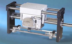
Basics of Rolling-Ring Linear Motion
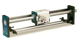
Rolling-ring drives are friction drives that convert the constant rotary motion of a plain shaft into a traversing action that moves an attached carriage. Used in positioning and reciprocating linear-motion applications, rolling-ring linear drives are mechanical alternatives to electronically controlled linear-motion drive systems.
Rolling-ring drives run on a smooth, unthreaded shaft. The rotary input of the motor-driven shaft is converted into linear output by the action of specially machined rolling-ring bearings. The mechanism generating the linear output is friction between the rolling-ring bearings and the shaft.
Rolling-ring drives come in both fixed-pitch and variable-pitch models. Fixed-pitch versions operate more or less as threadless screws. These drives handle incremental positioning and PLC-controlled operations such as in metrology machines. The required controls are similar to those in conventional screw-based drive systems.
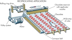
For many applications, however, variable-pitch rolling-ring linear drives eliminate the need for electronic controls, as pitch can be precisely adjusted and even set to zero. Travel direction and linear speed are mechanically controlled independently of the motor. This simplifies both design and operation of the linear-motion system. Variable-pitch rolling-ring drives are used in reciprocating linear-motion applications such as ejecting, cutting, spraying, and winding.
Rolling-ring drives hold several advantages when used in appropriate applications. These include:
- Long lifespan (10 years or more) when load is properly supported and coupled to the drive unit.
- Automatic reciprocating linear motion without complex controls.
- Variable traversing speeds ranging from 0 to 4.2 m/sec. Speeds can also be separately set for each direction, even though shaft-rotation speed is constant.
- Variable traverse length and position.
- Near-instantaneous, automatic reversal without changing drive-motor direction.
- Low operating and maintenance costs.
How they work
In either fixed or variable-pitch rolling-ring linear drives, the drive unit sits on a smooth, unthreaded shaft. High-quality drives use only induction-hardened, ground, and finished steel shafts with minimum surface hardness of 50 Rc, diametral tolerance of h6, concentricity tolerance (ISO 1101) <0.1 mm/m, and surface roughness Ra <0.35 μm.
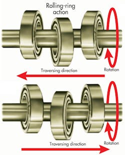
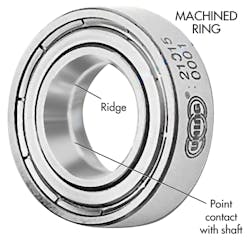
Three or four rolling-ring bearings are housed inside the drive unit. Each bearing is specially machined to form a “ridge” — a specially shaped running surface — around the inner race. The shaft contacts each bearing on a single point of this ridge. When the shaft rotates, the bearings essentially roll along the length of the shaft and, thus, move the payload attached to the drive-unit housing.
The bearing angle determines the drive’s travel direction and linear pitch. In the variable-pitch version, the angle of the bearings relative to the shaft can be adjusted with a pitch-control lever. Turning the lever pivots the bearings on the shaft, which increases or decreases the linear pitch. This is accomplished without changing shaft-rotation speed. Thus a variable-speed linear drive does not need clutches, cams, or gears.
On Amacoil-Uhing variable-pitch rolling ring drives, the linear-pitch control lever is manually adjusted to a setting on a scale. There are 100 discrete notched settings on the scale, and each increases or decreases pitch by 0.01. This enables a 10:1 turndown of the linear pitch. For instance, if the drive is set with a maximum pitch of 0.25 in., the operator can use the pitch-control lever to turn down the pitch to 0.02 in.
Other advantages
The constant point contact between a rolling-ring bearing and the shaft prevents backlash. Because the ridge of each bearing is a point of continuous contact with the driveshaft, when the shaft rotates, its rotary motion immediately converts into linear output. There is never free movement or play between shaft and bearing.
Because the shaft on which the rolling-ring drive runs has no threads, debris cannot clog the shaft or cause jams. Clogged threads can cause other linear-motion drives to churn, which can subsequently damage expensive system components. In a rolling-ring drive, if an object blocks travel of the drive nut, the shaft simply slips until the blockage is cleared.
When a rolling-ring drive reaches the end of the travel stroke, it contacts a hard end-stop which flips a spring-loaded reversal lever connected to the bearing assembly inside the drive unit. When actuated, the reversal lever turns the bearings on the shaft to immediately change the drive’s travel direction. The shaft rotational direction does not change. Reversal is purely mechanical and does not require electronic controls. Depending on the size of the unit, load, and speed, reversal is near instantaneous, typically within a few hundredths of a second.
Maximizing thrust and longevity
In rolling-ring drives, linear motion results from friction generated at the point of contact between the bearing’s inner race and the shaft. For this reason, no lubricant is used which would interfere with metal-to-metal contact between shaft and bearing. Oil, silicone, graphite, and other friction-reducing substances are taboo with rolling-ring drives.
The thrust a rolling-ring drive delivers depends on the diameter of the bearings and the number of bearings in the drive. Four-ring drives provide twice the axial thrust of three-ring drives. A large rolling-ring drive can provide as much as 800 lb of thrust. It is still, however, a friction drive, which means thrust capacity can be overcome by a payload that is too heavy, moving too fast, or subject to a significant overturning moment.
To ensure a rolling-ring drive delivers its full rated thrust, the payload must be attached such that it does not create an overturning moment. Designers can accomplish this in a number of ways, such as using a linear-bearing slide load carrier, as shown in the accompanying graphic. The load-carrying platform on top of the drive rides on linear bearings. Two yokes extend down on each side of the unit but do not attach to the drive itself. The drive simply pushes against the yokes to slide the load carrier back and forth. Thus, the carrier completely absorbs the full weight and any forces created by the payload. The drive does nothing but the work for which it was designed: push.
If a load carrier is not used and the payload bolts directly to a rolling-ring drive, the drive is unable to “float.” It must then bear the weight and all forces created by the payload. Moment loads are transferred to the shaft/bearing point interface and this dramatically reduces the thrust of the drive unit, while increasing wear on the bearings.
Similarly, fast-moving, heavy loads can have significant inertia. If the payload is not correctly supported, suddenly reversing the rolling-ring drive forces the unit to counteract this inertia. Depending on the magnitude of inertia and size of the unit, this can cause the drive to slip. In extreme cases, the drive unit may even be pulled back on the shaft against the direction of travel. Again, this generates wear on the inner race of the bearing, which will be evident as the drive then fails to deliver the expected thrust.
Suitable applications
Rolling-ring technology is not new — it has been around since the 1940s. The technology is well developed, and the units can generate intricate patterns of motion. Because it is a friction drive, however, it is often a good idea to consult knowledgeable suppliers when considering rolling-ring drives for linear-motion applications. The effects of linear speed on heavy payloads, and the way payloads attach to the drive, are two issues that should be discussed.
If application requirements are within the capabilities of a rolling-ring drive, significant savings are possible on setup time and programming. Reliable rolling-ring drive suppliers will provide technical support, determine if a rolling-ring drive is suitable for a specific application, and offer assistance in selecting the right size rolling-ring drive. Some manufacturers also offer sizing software, online configuration tools, and downloadable CAD models to aid in the design process.
Resources: Amacoil
