This file type includes high-resolution graphics and schematics when applicable.
Engineers who build components to last are naturally concerned with wear. There are different types of wear, and some engineers may induce wear purposely for varying reasons. Three types of wear are abrasion, adhesion, and corrosion. Each type has inherent problems and benefits that can be affected by materials, lubrication, and surface finish.
Abrasive
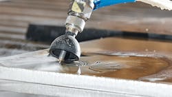
There are two common types: two-body and three-body abrasion. Two-body abrasion refers to surfaces that slide across each other where the one (hard) material will dig in and remove some of the other (soft) material. An example of two-body abrasion is using a file to shape a workpiece. Three-body abrasion is where particles between the two surfaces remove material from one or both surfaces. The tumbling process is an example of this.
Tumbling involves using particles to sand and polish the surface of a part. The particles that cause abrasion are often called contaminants. Contaminants are anything that enters a system that creates abrasion. While lubrication is imperative, an active lubrication system can introduce contaminants that cause abrasion. Filters remove contaminants and are one of the reasons proper maintenance and replacement of filters is important. However, the lubrication, or the additives in it, can react with the metal, creating a thin monolayer of contaminants that also make proper lubrication selection important to reduce wear to your equipment.
Surface roughness is another important variable for wear. Two-body abrasion is reduced by having smoother surface roughness. For example, a journal or sleeve bearing made out of a softer material will slide against a harder drive shaft with little to no abrasion due to the surface finish. Using materials with similar hardness is generally not advised. The reason for the softer bearing material is to further reduce wear. Contaminants can become embedded into the softer materials and stop three-body abrasion from occurring. This technique might damage the bearing, but is preferred as it is designed to be relatively easy and more cost-effective to replace than a drive shaft. The rougher surfaces can increase the coefficient of friction and micro-peaks can break off, contributing to contaminants that are related to abrasion.
Adhesion
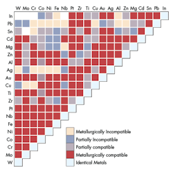
Surface roughness also contributes to adhesion. For this type of wear a material’s compatibility will be important. Compatibility does not mean materials that work well together; rather, that the materials “like” each other, causing them to stick together. This compatibility forms a bond causing parts to seize and even become cold-welded together. There are a few general rules to follow for material selection to make sure unwanted adhesive wear doesn’t occur. Materials that make contact with one another, in general, should:
• Not dissolve in the other
• Not, in given environment and other conditions, form into an alloy
• Not be identical (e.g., an aluminum shaft with an aluminum bearing)
• Have at least one metal from the B-subgroup (e.g., elements to the right of Nickel, Palladium, and Platinum on the periodic table).
Adhesion is possible to calculate. The adhesion and abrasive wear calculations share the same formula; however, it can vary by as much as +/-20%. This inaccuracy is due to constant changing surface conditions and lubrication during operation. It may be better than no data, but designers need to be aware of the limitations and accuracy of the formula. Trying to calculate or predict wear is made more difficult if components have non-conforming geometries, such as when gear teeth and cams are involved. These components can have difficulty staying properly lubricated. To reduce adhesive wear, sometimes corrosive wear is purposely induced.
Corrosive
Chlorides, phosphates, or sulfides can be added to induce corrosion and reduce a more destructive adhesive wear. Corrosive wear is more often thought of as something you want to prevent. Rust, or oxidation, is the No. 1 form of corrosive wear. Lubrication, material selection, surface finish, including coatings—like in abrasive and adhesive wear—are the main factors to consider.
Noble materials are noted as having non-corrosive properties. Gold specifically is used in electronics as a coating due to its ability to resist corrosion. Noble materials are often used sparingly or in minimal waste processes due to their cost. Other materials are self-anodizing. Aluminum is known for reacting with oxygen to form a layer of aluminum oxide that will prevent oxidation.
Iron and ferrous materials not only are prone to rust, but will flake off, exposing another layer allowing the oxidation to continue the degradation process. In the case of self-anodizing materials, slight abrasions or even stresses can cause crack propagation or scrap off the aluminum oxide, allowing the corrosive wear to continue.
Stress affects corrosive wear. Stress corrosion and corrosion fatigue will significantly accelerate corrosive wear. The difference between these types is the loading situation. Static loads cause stress corrosion where more dynamic loading, such as cyclic loads will cause corrosion fatigue.


