What’s the Difference Between the Elastic Modulus and Kinetic Modulus?
This file type includes high resolution graphics and schematics when applicable.
In 1807, Thomas Young discovered that stress in a material (F/A) is linearly proportional to the strain (change in length/original length) in that material. This, in turn, led to the discovery of a proportional constant, the elastic or Young’s modulus, E, and the equation, ÉE = σ, where É is strain and σ is stress, the foundation of stress analysis.
However, this relationship between stress and strain in a material is linear only when the force applied is within certain limits, and only under static loads. That hasn’t stopped engineers and designers from misapplying Young’s modulus outside those limits and under dynamic loads.
This misuse of Young’s modulus does not cause problems if the structure is so over-designed that the bulk conceals the nonlinear relationship. But the emphasis on reducing weight and size in structures and components leads to some materials being used close to their design limits. This requires a more precise definition of modulus, the kinetic modulus, which can be used under any load conditions to describe a material’s or part’s resistance to stretching or deforming.
The Kinetic Modulus
The basic equation for the kinetic Modulus is:
Ek = f(σ, ε, σy, t, T . . . .)
The exact equation for Ek can be determined from the conventional stress-strain curve for a material. The equation will depend on the magnitude and type of load applied to a component.
Using the term kinetic modulus is simply another way of implying that the instantaneous ratio of stress to strain varies with the fundamental characteristics of materials in motion. The type of motion and resistance to that motion defines the range of kinetic modulus values. In most applications, there are three common types of motion and resistance:
- No motion/static load resistance
- Unidirectional motion/impact resistance
- Cyclic motion/vibration resistance
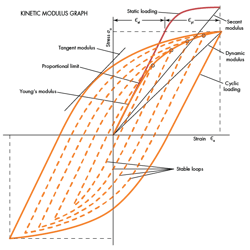
Static Load resistance normally implies stress-strain condition within the proportional limit, in which case Young’s modulus applies. The modulus is determined by the slope of the linear portion of the stress-strain curve via this equation:
E = σ/ε
Traditionally, Young’s modulus is used up to the material’s yield stress. (Yield stress is the stress at which a material begins to deform plastically. Prior to the yield point, the material deforms elastically and returns to its original shape when the applied stress is removed.) In many structures, stress concentrations (such as welds and joints) cause local yielding even though the applied stress is quite low. Local yielding arises when the applied stress is above the proportional limit but below the yield stress, which ranges from one-half to two-thirds of the yield stress, depending on the material’s ultimate strength.
For static loads above the proportional limit, the secant modulus must be used. This modulus accounts for local plastic deformation and resulting strain hardening or softening. The secant modulus is derived from the slope of a line connecting the origin of the stress-strain curve to the applied stress. Its equation:
Es = σa / εa = σa / (εel +εpl)
For materials stressed in the plastic region, stress and strain are related by Ludwig’s equation:
σ = Kεn
where coefficients K and n describe the deviation of the stress-strain curve from a straight line as the material plastically deforms.
Impact resistance implies a wide range of modulus values depending on the stress distribution throughout a structure. Under impact, the kinetic modulus can vary from zero at the ultimate strain value to the elastic modulus. Resistance to motion under these conditions is described by the tangent modulus, Et, which is found from the tangent to the stress-strain curve or hysteresis loop. The equation for Et is:
Et = nEs = n'Ed
Where the unprimed variables refer to unidirectional loading and the primed variable refer to cyclic loading.
Vibration resistance implies a wide range of modulus variables depending on the amplitude of stress applied and the yield strengths of the material. Under cyclic loads, the relationship between stress and strain is described by a hysteresis loop, with the area inside the loop being absorbed by the material in one cycle.
Under cyclic loading, local plastic deformation neither hardens nor softens a material, so the material displays a variable resistance to motion. After about 100 cycles, the material stabilizes and resistance to motion can be described by the so-called dynamic modulus (also called the cyclic secant modulus).
Dynamic modulus accounts for strain hardening or softening and is found from the slope of the hysteresis loop. It’s equation is:
1/Ed = 1/E + εpl/σa
where the relationship between Éa and σa is again described by Ludwig’s equation except that K and n are modified to account for cyclic loading.
How the Kinetic Modulus Changes
As noted above, the kinetic modulus is hardly constant; it varies with stress, strain, yield strength, and time. The effects of stress and strain are indicated by the use of different moduli for various load conditions. However, variations with yield strength and time are less obvious and only show up after extensive testing.
Measurement of dynamic modulus have revealed that the higher the yield strength for a given stress amplitude, the higher the dynamic modulus during motion. The relationship between dynamic moduli for high and low yield strength material has been found to be:
(Ed)h = (σh'/σl')(Ed)l
where h and l refer to high and low yield strength, respectively.
For high-strength, low-alloy steel (50 ksi yield strength) and mild steel, the ratio of σh/σl is 1.6. That means HSLA steel has the higher dynamic modulus and, thus, is stiffer. That means that in a stiffness control application, one with cyclic loads above the proportional limit, higher strength materials resist motion better. This contrasts with traditional theory which holds that because modulus is constant, strength is of no value in resisting vibrational loads.
The effects of time are revealed by studying the change in modulus as the number of stress cycles increases. Tests show that dynamic modulus decreases with time, the rate of decrease depending on the stress amplitude. In general, the dynamic modulus remains relatively constant for stresses near the proportional limit but drops off rapidly as the amplitude of the stress reversal nears the yield strength.
Design Ramifications
Tests on cyclically loaded parts indicate that you can have considerable plastic deformation despite the fact the applied stresses are quite low. Deformation is normally confined to areas around welds, joints, bolt holes, and geometric discontinuities, indicating that these areas are the main points of energy dissipation in structures. (The amount of energy dissipated is the area inside the stress-strain loop.)
In general, these points are subjected to multiaxial stress which significantly affects a part’s damping energy. Because most structures have a considerable number of discontinuities, researchers believe that the multiaxial stress distribution and corresponding hysteretic energy dissipation exert an important influence on natural frequency.
Evidence supporting this conclusion is that FEA on structures typically predict higher natural frequencies than are actually measured. This discrepancy can be explained by the widespread use of rigid joints rather than flexible ones, which would better describe or model plastic deformation at these points.
The important characteristic of plastic deformation at a joint is that the modulus is neither constant nor linear. Instead, it decreases with increasing load amplitude. Therefore, natural frequency, which varies directly with modulus, also decreases at high load amplitudes. This is important because natural frequency governs the design thickness and shape of structural parts.
Here are a trio of relationships between structures and the stress-strain curves and loading:
- Structures of constant yield strength: As cyclic load amplitude increase, the natural frequency decreases. As thickness decreases, stress amplitude increases and natural frequency decreases.
- Structures subjected to constant cyclic-load amplitude: As thickness decreases (with yield strength held constant), stress amplitude increases and natural frequency decreases. As yield strength increases, dynamic modulus increases and natural frequency increases.
- Structures requiring weight reduction (or thickness decrease): As thickness decreases while yield strength remains constant, stress amplitude increases, and dynamic modulus and natural frequency decrease. With a 10 to 20% decrease in thickness and a 50% increase in yield strength, an increase in dynamic modulus offsets the decrease in section modulus to maintain a constant natural frequency.
Looking for parts? Go to SourceESB.
This file type includes high resolution graphics and schematics when applicable.
