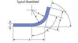
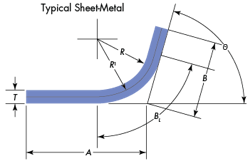
When engineers need to make curved or bent pieces of sheet metal, they use company-written tables, rules of thumb, and guesstimates to determine the length of straight stock needed for bending into a precisely measures curved part. But these methods are unavailable to some engineers. Even if they were, the required stock length depends not only on end radius, material thickness, and angle of bend, but also on the specific material being used.
Fortunately, there is a series of equations that are valid for all materials that can calculate bend allowance and bend length. If the material’s strength and ductility are known, the equations can be used directly. If not, they can be used with data from a simple test bend to determine the material properties, and then applied to the bend at hand.
BL=( θπ/180)(R +(T/2))
The bend allowance (Ba) for outside measurements A and B is related to bend length (BL) by:
Ba=( θ/90)(2(R+T)- BL)
However, when materials undergo plastic deformation, as they do in bending operations, the neutral plane does not remain at the center of the sheet. Under these conditions, bend length can be found from Equation 1:
BL=( θπ/180)(R +C(T/2))
where C is related to the material’s ductility.
One indication of ductility is K, the ratio of a material’s yield strength to its tensile strength. Low-ductility materials have K ratios approaching 1.0, while highly ductile materials have K ratios much less than 1.0. Values of K have been determined for several common sheet metal metals. Applying linear regression with the bend-length equation yields the following equation for C:
C=0.668+0.326K2
Because sheet metals vary from batch to batch, K and C values are best determined from test-bending a material sample and computing new values, rather than relying on previously established values or published data. Both K and C are properties of the metal rather than geometry, so the test bend can be made on a sample of any convenient thickness and at any convenient radius.
Using the above equations and data from a test bend, K2 can be found from Equation 2:
K2=((2(R+T)tan(θ/2)-Ba)(180/θπ)-R)((1/T)-0.334)(1/0.163)
Using the equations: In practice, Equation 2 is typically used to determine K from a test bend, then solved for Ba, the bend allowance for production bends. If needed, bend length can then be calculated from Equation 1.
For example, consider a 20-gauge (0.036-in.) low-carbon steel sheet that must be bent 75 deg. with an inside radius of 0.093. Bend allowance is needed to determine raw material requirements.
The actual material is not at hand, but a sample of the same steel in 16 gauge (0.60 in.) is available. The sample length is 3.23 in. and the sample is bent 90 deg. with a radius of 0.125. After the bend, the dimensions of A and B are found to be 1.506 and 1.857. Bend allowance for the test bend is:
Ba=A+B-L
=1.506=1.857-3.2
= 0.133 in.
From Equation 2, the value of K2 for this material is:
K2=(((2(0.125+0.06)tan(90/2)-0.133(180/90π)-0.125(1/0.06)-O.334)(1/0.63)
=0.597
Now, by solving Equation 2 for Ba, using the value of K2 just found and inserting the values for the thickness and radius of the production bend, the bend allowance for the production bend can be found:
Ba=2(R+T)tan(θ/2)-( θπ/180)(R+(0.334+0.163K2)T)
=2(0.093+0.036)tan(75/2)-(75 /180)(O.093+(o.334+0.163(0.597)(0.036)
=0.056 in.
If raw material calculations make it more useful to have bend length than bend allowance, B1 can be found from Equation 1:
BL=( θπ/180)(R+90.668+0.326K2(T/2))
= (75π/180)(0.093+(0.998+0.326(0.597))(0.036/2))
= 0142 in.
Nomenclature |
|
A=Straight line dimension on one side of the bend (see illustration), in. B= Straight line dimension on other side of the bend, in. Ba=Bend allowance, in. BL= Bend length, in. C=Ductility constant K=Ratio of yield strength to tensile strength L=Straight line length of piece before bending, in. R=Bend radius measures on inner surface, in. T=Material thickness, in. θ=Bend angle, ° |

