3D Printing Tips and Tech: Get to Know Those Acronyms
The following is a series of tips and techniques to help answer your questions about 3D printing. If you would like to contribute tips, or have questions about 3D printing, email me at [email protected].
With the rapid pervasiveness of 3D printing, confusion has begun to set in among some people regarding the different processes. Simon Caiger , Product Manager for JK Lasers, says there’s so much misunderstanding, organizations are creating standards to generate better communication when talking about the processes in additive manufacturing (AM).
This article will give a few explanations and differences between these processes. To start, 3D printing and AM can be used interchangeably. Both are general terms that cover many types of processes; in this article, everything will be an AM process.
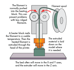
FFF vs. FDM: These are two of the most popular types of 3D-printing processes. The difference is a legal one. Fused deposition modeling (FDM) is a trademark process developed by Stratasys. This led members from RepRap to coin the term fused filament fabrication (FFF) for a general, more legal way to present the process that extrudes material through a nozzle (normally, but not limited to, melted polymers) to build parts up in layers. This process can have tolerances of about 0.002 to 0.02 in. (0.05 to 0.5 mm); the industry average is 0.008 in. (0.2 mm).
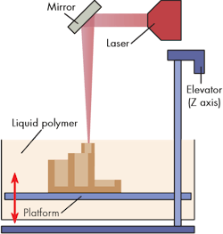
Ultraviolet (UV) curing is not SLA: UV curing is used in different processes, so this can lead to confusion. The main difference is if the process uses a UV lamp or a laser to setup the material. SLA is a vat process. A build tray is submerged in a bath of liquid photoreactive polymer or resins. A laser, not a UV lamp, is used to solidify the first layer of the part on the build tray. Then the build tray submerges again (~0.002 in. to 0.02 in.) and repeats this process until the part is built.
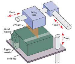
Another process capable of using UV curing is material jetting. This process is often equated to an inkjet printer that can build up layers in the z-axis, too. Material jetting is referenced in many types of acronyms and trademarks. Drop on demand (DOD) is a general terminology, and there are trademarks such as Polyjet from Stratasys.
Material jetting is convenient, since it can mix colors and properties as it prints without stopping. This technique is capable of high-resolution prints with layers that are 0.002 in. thick. Just as is the case with any other process, the higher the tolerance or resolution, the longer the print time.
Mark Barfoot, President of Additive Manufacturing Users Group, mentioned that 3D Systems produces the Projet 3510, which uses the material-jetting process. However, 3D Systems also makes an SLA machine named the Projet 7000. The name might seem similar, but the processes are different.
SLA and DLP: Photo-polymerization is another general term that, simply put, uses light to solidify a liquid polymer or resin. Examples include, but are not limited to, SLA and digital light process (DLP). These processes are both bath or vat processes with a photosensitive polymer or resin. The SLA uses a laser, and DLP uses a projector, to solidify the material. SLA can take longer, because the laser must travel the entire path of the part for each layer. A projector may expose the entire layer cross-section at the same time. This means the power of the lamp will be important to part size, and is often why DLP is performed with small parts.
Another miscommunication is that DLP is done from the bottom, whereas SLA is from the top. However, both processes can take a top-down or bottom-up approach. Right now, though, the trend is bottom-up for DLP top-down for SLA.
Barfoot explained the current trend may be due to the optics of the laser. If used in the bottom-up approach, problems could arise when traveling through the glass as refraction. Thus, reflection might be why the top-down approach is preferred for the SLA process. The top-down approach limits the travel in the Z axis to the depth of the basin, but the bottom-up approach will travel as long as the guide rails will allow. It also doesn’t require the basin to be full, since it’s working from the bottom. The part can lift out of the basin. As long as the working surface is submerged, the bottom-up process can continue.
Carbon 3D has been making headlines with its improved DLP print speeds thanks to a novel permeable material that allows oxygen in with the light to solidify material more rapidly. This isn’t a new process, but rather a new product used in the process. DLP is capable of the same resolution as SLA.
SLS vs. SLA vs. SL: The only difference between the SL and SLA abbreviations for stereolithography is that SLA is trademarked by 3D Systems. The process is the same regardless.
Ethan Burnham-Fay, from the University of Rochester’s Precision Instrumentation Group, says that from a quick glance, SLA and selective laser sintering (SLS) are similar. Both use lasers; however, they operate at different wavelengths. SLA utilizes lasers operating in the ultraviolet (UV) wavelength, which are used to cure epoxy within a resin. SLS employs higher-powered lasers to compact and sinter metal powders.
The requirements for both applications are very different, mainly because SLS requires high peak energy to physically compress the metal powders, while SLA can be used at lower peak powers depending on the photosensitive polymer in use. The power requirements are the biggest difference between the two laser systems.
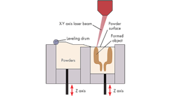
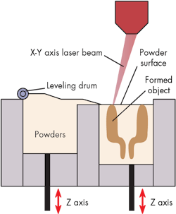
SLS is also commonly associated with the powder-bed process. This process uses a bed of powdered material (polymer or metal). A high-powered laser generates one layer of a part each pass, normally around 3.94 × 104 in. (10 µm) layers thick, and an industry-standard tolerance of 0.004 in. (0.1 mm). These can be altered by the laser’s properties, and material used in the process.
However, there’s also a powder-fed process. The name pretty much says it all: The process is powder fed through a head that sprays material into place while using a laser to sinter it. JK Lasers’ Caiger says that it’s possible to use this process to fix broken or cracked parts. It’s even possible to align the grain structure of the new material with that of the existing part. Consistent grain structure is not only important for mechanical properties, but corrosion resistance. This process can often have a post machining process, because tolerances may be difficult to control.
Some companies offer a three-step process where one machine will clad (put one material over another), measure, and grid the part. The lasers for these processes have a trend of using fiber lasers and LED sources. Polymers can be processed with a laser of around 30 to 100 W, where metals can go up to 1 kW.
Electron beam and SLS: This is a process with the same setup of a powder-bed or -fed process, but instead of a laser, it uses a beam of electrons. This can work well for titanium and stainless-steel parts. The surface finish isn’t as smooth as the SLS or SLM process, but this has been a desired feature in the medical field. The coarser finish means it can be more easily graphed or bonded to bone.
SLS and SLM: The difference in SLS and selective laser melting (SLM) is that SLM melts the powder while SLS sinters it. In both processes, the laser strength depends on how fast a part can be built, or the tolerances it can achieve. In SLM, laser strengths can range from 200 W to 1 kW for a single laser. For the powder jet processes, beam quality isn’t as important because there will be a post-machining process. However, it is important for the powder bed process.
SLS, SLM, and electron beam do have limitations. First, the availability of powders might be a problem, but as these processes become more common, selection is getting more diverse. Making sure the powder needed is readily available is important. The second concern is safety—you don’t want to inhale certain powders. Containment and ventilation will be necessary depending on the powders used. The third limitation pertains to the speed—3D printing is no longer just for one-offs. Michael Block from Stratasys mentioned that some companies have been testing 3D printing’s viability when it comes to mass production. Speed is important for this, but there’s an economical breaking point.
Many more processes and acronyms for 3D printing exist in the market, but these are the more popular AM processes.
Lamination
Another process, the lamination technique, may not be as popular. Still, techniques in this arena are generating interesting products and further reducing limitations.
Fabrisonic uses ultrasonic to create custom laminate metals. One machine its CEO talked about was a 3-axis arm with an ultrasonic cone that would continuously unspool foils over the tip to build up layers around 0.006 in. thick. The idea of this being used in the electronics and RF industries might be something to keep an eye on.
Mcor Technologies cuts, prints, glues, and presses layers of paper onto previous layers. This technique allows for high-resolution, full-color 3D models using the lamination technique.
Impossible Objects takes a similar tack—its lamination technique uses carbon-fiber sheets and prints a layer of polymer that’s heated to metal the polymer and then pressed to make carbon-fiber parts.
Standards and clear communication are crucial in the 3D-printing universe. Understanding the processes laid out in this article will help clarify which one will serve best for a given application, saving users time, money, and frustration.
