How to design a linear-motion system
Whether you decide to design and build your system from scratch using standard parts or buy one that’s engineered for you, making the right choices from the outset should help keep things moving for the long term.
Support and guidance
Building a linear system literally means starting from the ground up — with a structural-support system. The support system’s main component is typically an aluminum extrusion.
You can have the mounting surface of the base extrusion and the surface the linear guide mounts to machined for applications that require accurate positioning. For lower accuracy, transport-type applications, optimize bases to resist bending under load and to prevent distortion during extrusion instead.
This file type includes high resolution graphics and schematics when applicable.
A robust base lets the system rest on end supports only. Lighter extrusions may need intermittent supports along their lengths.
Guides attach to the base to facilitate motion. The main types are ball guides, wheel guides, and slide or prism guides.
Ball guides carry the heaviest payloads and have the highest stiffness. Their single or dual-rail configurations move with little friction. The downsides are higher cost and the amount of noise they generate.
Driving force
Drives move the carriage to the desired positions. The most common drive technologies are ball-screw drives, leadscrew drives, and belt drives.
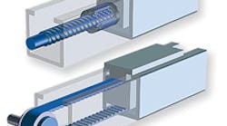
In a ball-screw drive, ball bearings travel along the grooves in a threaded shaft — the ball screw — and recirculate through a ball nut. Because bearings share the load, ball-screw drives have relatively high thrust capacity.
The result is absolute accuracy, defined as the maximum error between the expected and actual position, down to 0.005 mm. Systems with ground and preloaded ball screws are the most accurate.
The systems have thrust capacity up to 40 kN and high stiffness. Their critical speed is determined by screw root diameter, unsupported length, and end-support configuration. With a novel screw support, screw-driven units can travel up to 12 m and accept 3,000-rpm input speeds. Ball-screw drives provide mechanical efficiency of 90%, so their higher cost is often offset by lower power requirements.
Belt drives work in high-throughput transport applications with velocities up to 10 m/sec and acceleration up to 40 m/sec2.
Lubrication and seals for linear devices
Most guide systems and drive systems require lubrication. You can simplify future preventive maintenance by ensuring easy access to lubrication fittings. For instance, Zerk fittings installed on the carriage can feed a lubrication network that serves both the ball screw and linear-bearing system during installation and at periodic maintenance intervals.
Prism guides are maintenance-free. The polymer material of the slide has inherent lubricity, and lubricated felt wipers replenish lubricant each stroke.
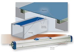
Seals keep lubricant in and contaminants out. One type is magnetic-strip seals — stainless-steel magnetic bands extending from one end of the channel to the other. The bands are fixed to the end caps and spring-loaded to maintain tension. They run through a cavity in the carriage so the strip is raised off the magnets just ahead of and behind the carriage as it traverses the system.
An alternate sealing technology, plastic cover bands, uses compliant rubber strips that interlock with the base extrusion, like a zip-top freezer bag. Mating tongue-and-groove profiles create a labyrinth seal that keeps out particulates.
One more consideration is how you will mount your motor. A motor housing and coupling must mate with the bolt size and bolt-circle diameter on the motor flange, motor pilot diameter, and motor shaft diameter and length.
Many motors have dimensions that meet NEMA standards, but others are manufacturer and model specific. In either case, flexible motor mounts machined from common blanks make it easy to mount to nearly any motor with guaranteed alignment.
Not every combination of drives and guides makes sense. In practical applications, you’re most likely to see leadscrews driving ball or slide guides; ball screws paired with ball or slide guides; and belts driving ball, slide, or wheel guides.
A ball-screw drive combines with a ball guide for repeatable motion and a stiff system that handles high forces and moments. Such systems work well in precision-positioning applications with high loads and high duty cycles, such as loading and unloading gear blanks on machine tools.
Belt-driven, ball-guided units are for high-speed, high-acceleration applications with heavy payloads and high moment loads. These units work on bases that span a gap and are supported either at the ends or intermittently. Palletizing cans is one application.
Belt-driven, slide-guided linear systems are lower-cost units that are quiet and need little maintenance. They work at moderate speeds and accelerations but excel at managing impact loads. Adding a magnetic cover band makes this type of system suitable for environments with a high particulate content and wash-down requirements such as sheet-metal spray treatment.
Because wheel guides need less maintenance than ball guides, but more than slides, wheels driven by belts are another moderate-cost, low-noise, low-maintenance option. These systems achieve high linear velocities and accelerations and are often found in packaging and filling machines.
Make or buy?
When considering whether to make or buy a linear system, think about the engineering time and expertise you’ll need to design the system from scratch. You’ll need to calculate linear and radial-bearing life, ball-screw life, ball-screw critical speed, and deflection of the support profile, among other parameters. You’ll also need to select a lubricant and lubrication system, and design a cover to keep out contaminants.
You could supersize the system to shorten design time, but the final system will cost more and take up more space. And you’ll still have to do a basic engineering review to make sure you didn’t miss anything.
On the other hand, if you decide to buy your linear system, there will be times when standard catalog products do not meet the requirements of the application. You may need to have the vendor modify a standard product or design a component from scratch for you.
A vendor with a broad range of products and engineering capabilities can partner with you to solve the problems your application presents. The end result is that you’ll save time and money and speed up your development cycle.
Application engineering example
Engineers walked three distinct applications, each from a different market, and each with a 500-lb load. They arrived at three very different end results due to the variations in environment and application details.
Application 1 – Packaging: A linear unit is needed to vertically position an automatic shrink-wrapping machine. For safety reasons, the vertical orientation drives us toward a ball screw. While the sealing, speed, and accuracy requirements are low, the moment loading is quite severe due to the rotational wrapping motion. The high moment load drives us to a ball-guided carriage.
Application 2 – Machine automation: A linear unit needs high acceleration and smooth operation for a paint-spray booth. The 1.5-m/sec speed requirement points to a belt drive. Additionally, the application needed to be maintenance-free, which drives the selection of a slide guide. Although the overhanging spray arm could present a severe moment, using two synchronized slides eliminates the potential moment.
Application 3 – Dispensing and filling: A linear unit is needed to quickly position the dispensing head. Throughput is the most important matter; a belt-driven, wheel-guided unit can deliver the highest speeds. Zip-lock sealing protects the unit from spills or splashes. A slightly larger frame size supports the underhanging dispensing head.
Web-based sizing and selection
Need to design a custom linear system while enjoying the cost and time savings of using standard components? Try Web-based sizing and selection tools linear-system vendors offer.
One example is Linear Motioneering from Thomson. The user enters key application parameters that the tool inputs into calculations such as linear bearing load/life, ball-screw load/life, and ball-screw critical speed.
It converts calculation results into a listing of products that meet the requirements. Output listings, ranked by cost, include 3D models, pricing, delivery times, and ordering information.
Here’s a step-by-step look at how to get the most out of Linear Motioneering and tools like it.
Step 1: Establishing the system orientation
Pick the orientation of your application: inverted, vertical, horizontal side or horizontal. Then choose the mounting configuration: fully supported, end supported, or intermittently supported.
Step 2: Set positioning requirements
Enter the stroke length from hard stop to hard stop. Select a framework for defining positioning requirements — accuracy, repeatability, or maximum allowable backlash — and set the positioning requirement value.
Step 3: Disclose environmental conditions
Knowing these conditions is critical to choosing the right material, cover strategy, and lubrication scheme. Select clean, water/chemical spray/fog, impact/press application/vibration, moderate to heavy dust-particulate count, high pressure/temperature wash down, water/chemical splash, or clean room. The application will recommend linear slide options — such as chrome-plated, stainless-steel, or Raydent-surface ball guides, CR linear bearings, or polymer plain bearings — that you can change later.
Step 4: Enter load and applied force
Load is the weight supported by the carrier or saddle supports, including the payload, fixturing, and tooling. Enter the X, Y, and Z coordinates of the center of gravity of the load with respect to the center of the carriage or saddle by entering X, Y, and Z values. You can also record an applied or external force, which the tool will assume acts at the center of gravity of the load.
Step 5: Set up move profile
Enter the move distance, move time, and dwell time which the tool will convert into acceleration rates. Choose a system from the list the tool will present.
Next, the tool creates recommended move profiles for the selected system — a green maximum-acceleration profile, a red minimum-acceleration profile, and several in between. Choose your preferred profile and desired acceleration rate. You can also enter your own acceleration rate.
Based on the chosen profile, the tool calculates safety factors, bearing and drive loads, and ball screw critical speed.
Thomson Industries Inc. • Thomson’s Linear Motioneering Web-based sizing tool:
“Component-life theory comes down to earth,” Machine Design, Dec. 13, 2007
About the Author
James Marek Business Unit Manager • Thomson Systems
Thomson Industries Inc. • Radford
Voice Your Opinion!
To join the conversation, and become an exclusive member of Machine Design, create an account today!

Leaders relevant to this article: