The difference between linear motors and linear mechanical devices
To fully appreciate the chief advantages of linear motors, it is helpful to compare them to ballscrews, another high-precision rotary-to-linear transmission system. Although typical ballscrews are roughly 90% efficient, servomotor efficiency (typically 75% to 80%) — plus losses introduced by the coupling and gearbox — reduces the power supply going toward actual work to 55% in some cases. In comparison, typical linear motors drive loads directly, which boosts overall efficiency.
Linear motor evolution
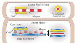
Linear motors are sometimes described as rotary motors cut open and rolled out flat. In fact, some of the first linear motor designs are just that. When the iron core “flat linear motor” with this design made its debut, it earned market share as a powerful and efficient alternative to other forms of linear transmission systems. However, its efficiency is limited by losses caused by eddy currents and cogging, which in turn limits this motor's suitability for high-precision applications.
Next, the coreless (U-shaped) linear motor was developed to address the iron core motor's problem areas. The “U” has its own advantages and drawbacks: The innovative U-shaped design addresses the losses from eddy currents and cogging, but can introduce lower motor stiffness and greater heat generation, which limits its use in ultra-high-precision applications.
For these ultra-high-precision uses, linear motors first appeared to be the Holy Grail of motion control, offering the promise of infinite positioning options and super-high efficiency. However, in some arrangements, heat from the motor's inefficiency is channeled directly to the work point. This increases the amount of work the linear motor is able to perform, but thermal growth caused by the generated heat complicates submicron positioning.
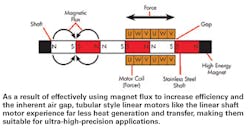
Subsequently, linear shaft motors were developed. These units consist of a stack of permanent magnets contained in a tube, plus a forcer of cylindrically wound coils. As we'll explore, linear shaft motors are optimized for the most power-efficient linear transmission possible, while also maximizing stiffness.
Motor design basics: Lorentz law and Fleming's law
The basic law behind motor design is Lorentz force law. This law states that the amount of force (F) a motor can generate is equal to the current (I) in the winding, times the magnetic field strength (B), times the vector cross product (X), times the length of wire in the wire spool (L).
Therefore, in order to develop a more efficient linear motor, the amount of current (I) must be reduced. To do this — while maintaining the same force output — the remaining variables of Lorentz force law must be both increased and optimized.
A recent study by University of Virginia (UVA) researchers found that the linear shaft motor uses roughly 50% less input power to achieve the same work output of a comparably rated coreless linear motor. We will now explore each aspect of Lorentz force law and see how the design achieves this efficiency boost.
The vector cross product (X): Fleming's law (often called the left-hand rule) helps us to understand that the optimal crossing vector for current to cross the magnetic field in order to create linear motion is 90°. The design of a traditional linear motor arranges the coil to have between 30% and 80% of its length at a 90° angle to the magnetic field. The rest of the coil is basically a return path, which creates losses due to added resistance. In addition, this return path can generate renegade forces that oppose the intended forces. In comparison, the cylindrical design of the linear shaft motor allows 100% of the coil to be at the optimal 90° crossing vector. No additional forces are generated besides the intended linear force.
Length of wire in the wire spool (L): This is where the design gets tricky. Adding too much length increases losses due to added resistance. The linear shaft motor balances length of wire with losses due to added resistance. In the motors tested by UVA, the coil length of the linear shaft motor is about 1.5 times the length of the coreless linear motor.
The amount of force developed in a given magnetic structure is a function of the flux density at the air gap between the components that move relative to the stationary segment. Because the reluctance of air is roughly 1,000 times greater than that of steel and directly proportional to the air gap length, minimizing it reduces the magnetomotive force (MMF) required to generate a given field strength. MMF is also a direct function of the amount of current supplied, so reducing this parameter dramatically decreases power losses — as the losses are proportional to the square of the current.
Practical matters
How is linear shaft motor efficiency useful and practical in general automation? To find out, let's consider two aspects of critical importance to engineers who specify motors: Heat and lifetime cost.
All linear motors heat up, due to wasted energy. When this heat is generated, it must go somewhere. The first major side effect of heat is thermal growth of the load to which the coil is attached. Further, the bearings, grease, and any sensors in the general area are also subjected to this excess heat. Over time, heating and cooling cycles can have negative effects on both mechanical and electronic components. In addition, thermal growth is likely to cause issues with binding and increased friction.
UVA testing confirms that even when both motors are attached to identical plates — with equal temperature rise within the coil - the heat transferred from a linear shaft motor is about 33% less than that from a comparably rated coreless linear motor. (In the UVA tests, the plates measured 100 × 150 × 10 mm. Both motors operated at 10 lbs of force for 24 hours. Temperature rise at the coil registered 41.3° C; at the coreless linear motor plate, 30.8° C; and at the linear shaft motor plate, 23.1° C.)
By requiring less energy, the cost of operating the system also decreases. Assuming the U.S. average cost per KwH of 12.17 cents, the annual operating cost of a coreless linear motor is $540.91, while the operational cost of the linear shaft motor is $279.54, measured at the ac supply to the servo drive.
For more information, call (540) 633-1677 or visit nipponpulse.com.
About the Author
Voice Your Opinion!
To join the conversation, and become an exclusive member of Machine Design, create an account today!

Leaders relevant to this article: