By 2040, 54% of new car sales and 33% of the global car fleet is predicted to be electric.1 More than six countries have announced a ban on internal-combustion engines. China is expected to be the largest market for electrical vehicles (EVs), which is pushing automakers to come up with aggressive rollout plans for EVs.
Some of the important trends driving EV development are getting more than 200 miles out of a charge, pricing below $40,000, fast charging (such as less than 30 minutes for an 80% charge), increasing fuel efficiency over a longer range for hybrids, and developing autonomous vehicles and electrification for not just cars but also industrial, public service, and mass transportation vehicles.
For the electric powertrain, engineering focus is on the price and size of battery packs, motor efficiency that affects driving range, and the tradeoff between drive range or performance with the ever-increasing driver experience requirements and features. Energy storage needs to be designed so that it obtains the required energy and power density in each battery cell as well as the overall pack. The pack has to be thermally regulated so that it will not overheat. Energy storage has to be monitored and optimized while driving.
The motor and power electronics must be optimal for the architecture, weighing efficiency vs. performance vs. cost. Here also, thermal management and reliability are important issues. The power electronics need to be reliable over a wide range of operating temperatures, and design is a challenge with the inverter and motor inside a single casing.
Applying the skills of computational-fluid-dynamics (CFD) experts traditionally has been helpful for electric-powertrain, component-level design, and to expose underlying limiting phenomena. However, this method of relying on CFD experts can result in either limited deployment of such tools for product programs or in under-achievement of the expected design efficiency.
A new approach, where powertrain designers can use the CFD tools easily from earliest design phases to evaluate prototype designs and optimization, is gaining traction among OEMs and Tier-1 suppliers. This front-loading, designer-centric approach rests on three elements:
- CAD-embedded CFD that allows complex CFD simulations to be done by non-CFD experts in the native CAD environment of designers.
- Simulation automation and a built-in database to allow engineers to achieve reliable and accurate results.
- Seamless integration with electronic design automation (EDA) and system simulation tools.
Using this approach, we have seen results that reduce the time and cost as much as 60%.2 This article illustrates the use of a front-loading, designer-centric simulation approach for electric powertrain and gives an overview of the benefits design engineers can get from deploying this approach in their work.
Efficient Battery-Pack Design and Prototyping
The example shown here is of an EV for recreational use in rough road and ambient conditions made by a company in Brazil.3 The vehicles are air-cooled with a 4-kW/h battery pack. The company obtains battery packs, or battery cells, from their suppliers, and then integrates them into its vehicle designs.
The design engineers needed to figure out what kind of cooling they would need with this particular battery pack so that the vehicle could fulfill its objective in harsh climatic conditions. Evaluation of design changes on battery thermal behavior with implications for pack reliability in real-world operation is ideally suited for using a CAD-embedded CFD simulation approach.
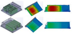
Engineers at this company leveraged CAD-embedded CFD software, FloEFD, for its battery-pack design optimization (Fig. 1). Starting with an initial CAD design of the battery pack, the engineers quickly simulated dozens of scenarios to explore the battery thermal behavior with changes in the battery’s design. Through this process, they reached an optimized battery-pack design much more quickly than if they had to send out their models for CFD analysis using the traditional CFD approach, where significant engineering efforts would have been dedicated to CAD-to-CFD translation.
1. Initial battery pack design (top) and final design (bottom).
Through these simulations, they were assured that the cooling system would be adequate for the harshest cases, such as driving on a long steep uphill with the vehicle loaded, when the asphalt is hot, or starting the vehicle when it has been parked outside on a sunny summer day. The simulations were instrumental to understanding if use-conditions could negatively affect battery life and which should be avoided by customers, as well as for devising strategies to mitigate liability issues that can be caused by misuse or random unpredictable system failures.
Traction Motor Design and Powertrain Integration Optimization
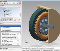
Traction motor design for EVs is a complex problem that requires accurate considerations of motor electromagnetic and thermal behavior and their dependence on motor architecture and materials. The problem becomes even more challenging for electric powertrains, because motor design must achieve the required performance metrics within the constraint of weight and volume targets. Using a simulation tool such as MotorSolve for traction motors brings powerful analyses to design engineers’ desktops (Fig. 2).
2. A 3D simulation of a traction motor.
Attributes such as template-based framework for commonly used motors, automatic winding generation, and material database makes it a designer-centric tool. It allows motor designers to simulate uniformity of magnetic field distribution, calculate losses, and evaluate appropriate motor-cooling designs (Fig. 3).
3. Example tests run in simulation: magnetic field (left), back EMF waveform (middle), and thermal management (right).
This application-oriented, motor design software has been benchmarked against data for commercial motors and demonstrated very good agreement. The motor-efficiency map is especially important because it dictates efficiency during real-world operation of an EV and thus plays a critical role in dictating electric drive range.
The results can be seamlessly imported into the 1D system simulation software, FloMASTER, which allows both motor design engineers and powertrain engineers to collectively evaluate the impact of design changes and optimize powertrain thermal-management configuration to ensure desired electric drive range is achieved in real-world driving conditions (Fig. 4).
4. The motor’s data can be imported into a vehicle thermal-management network design to observe the effects on the motor’s thermal behavior when it is put into the system.
Accurate Thermal Simulation for Power Electronics Design and Reliability
The design of power-electronics modules such as IGBTs or MOSFETs is heavily influenced by thermal concerns. New substrate materials, thinner and thermally more conductive attachment materials, and accurate thermal-management designs are needed to decrease the thermal resistance of a given module.
When a new material or technology is applied, its thermal design and reliability has to be tested thoroughly before the module can be considered for production. For these reasons, accurate thermal simulation of power electronics is critical. A key challenge for such simulations is getting reliable thermal properties of components, which is not always readily available from suppliers.
The T3ster hardware technology enables engineers to run nondestructive thermal characterization tests on components. The structure function from these tests can be directly imported to the electronic cooling simulation software, FloTHERM XT. This experiments-to-simulation workflow removes the challenge of using simulation results for product development. Combining characterization measurements with simulation provides thermal simulation accuracy that has an error of less than 0.5%, ensuring that better reliability is built into a vehicle’s power-supply system (Fig. 5).
5. Using a combined measurement-simulation workflow delivers thermal simulation that is accurate to within <0.5% error.
The thermally characterized IGBT model then can be used in a CAD-embedded CFD tool, such as FloEFD, to run automated design of experiments studies to further optimize the component’s design.4
Connectivity Starts at the Designer’s Desktop
For electric powertrains, engineers have to evaluate numerous design options that vary in component material to potential tradeoffs between the battery, motor, and inverter to meet targets for electric-vehicle range, performance, and reliability. For this, their tools need to support a designer-centric workflow—from frontloaded CFD, to built-in databases, to automated tests and analyses, to EDA connectivity so that component-to-powertrain design engineers can use these tools to make product-level decisions without having to heavily rely on simulation experts.
Software engineers at Mentor have worked over the years to turn this vision of “CFD democratization” into a reality, making the jobs of electronics, electrical, and mechanical design engineers easier. This connectivity across domains is necessary for electrical and autonomous cars to be a market reality. With automated and sophisticated simulation and analysis at their fingertips, design engineers can use their time more effectively in product development.
References
1. “New Energy Outlook 2017” by Bloomberg New Energy Finance.
2. John Parry, “State of the Art Automotive Thermal Design by DENSO,” Engineering Edge.
3. Vitor Straub, “CAD-Embedded Battery Pack Design Optimization for Mobilis Electric Vehicle,” Engineering Edge.
4. Anton Saratov and Mike Gruetzmacher, “How to…Optimized an IGBT Cold Plate,” Engineering Edge.


