This file type includes high resolution graphics and schematics when applicable.
Across the globe, there has been significant investment into and expansion of many industrial segments requiring heavy-duty material handling systems. These applications often operate continuously, lift and transport loads ranging from hundreds of pounds to several tons of material, and are frequently located in environments—mines, power plants, shipyards, ports and terminals—with rugged operating conditions.
Large hydraulics have proven to be effective when a heavy mass needs to be moved under variable speeds using a system that can handle shock loads (sudden increases in the weight and mass of loads being moved) with the ability to deliver energy efficient and reliable performance—typically operating 24 hours a day, seven days a week.
Operational and Applications Criteria
The most common uses of hydraulic direct drive systems are for industrial applications moving heavy masses on a continuous basis with low speed and high torque, and especially high starting torque (~2000 kNm) for operations with frequent stops and starts. Steady, continuous high torque is essential—loads need to be moved as part of a constantly operating process, with minimal downtime and a limited number of failure points within the drive technology.
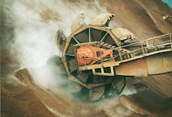
Key examples of these types of applications are ore and mining conveyors; feeders, crushers, drums, massive bucket wheel reclaimers, and excavators in mining and material handling applications; rail car unloaders and ship unloaders at ports and terminals; and bulk material movement systems at cement plants and coal-fired power plants.
Hydraulic direct drives also perform well in applications where “shock loading” occurs: Large, heavy loads are dropped onto moving conveyors, feeders, crushers, or turning drums that suddenly vary the load size by several tons during the course of normal operations. The drive has to be able to respond to the shock load without undue wear-and-tear on drive components and continue driving the material movement system smoothly.
Comparison of Drive Options
Different drive technologies can be used to operate these systems, each featuring different output characteristics of both speed and torque. They also have different components and operating characteristics which are helpful to consider.
- Electromechanical direct current (DC) drives: These systems, which do have wide use in many older installations, include DC motors that are typically rated for high rotation speeds—900 to 1800 rotations per minute (RPMs). To provide low-speed, high-torque operation, a mechanical gear reduction box is installed between the DC motor speed coupling and the driven shaft of the material handling system. There are several disadvantages associated with this configuration. The gearbox is essentially over-dimensioned and less reliable; the gear ratio is fixed, which does not allow flexibility in operating at optimum speeds; and the gearbox elements themselves also require maintenance and repair. In many of the operating environments described above, heat and dirt are unavoidable and can impact the gearbox operation significantly.
- Electromechanical variable frequency drives (VFD): This option is similar to the DC drive option and, in recent years, has replaced that technology. It combines a frequency converter, an electric AC induction motor, and a high-speed coupling, and provides a variable speed option. Similar to the DC system, the electric drive operates at high RPMs; for low-speed high-torque applications, a gear reduction unit is also required. The attendant inefficiencies associated with gearbox coupling of the drive system to the driven axis are similar.
- Hydraulic axial piston motors: These hydraulic motors have pistons driven by hydraulic pressure reciprocating in/out of chambers to rotate the motor’s output shaft, which can be coupled directly to the driven axis. Piston motors generally run at higher speed rotations; for the high-torque lower-speed applications under discussion here, it may be necessary to utilize a gear reducer to achieve lower speed operation.
- Hydraulic vane motors: These hydraulic systems are directly coupled to the driven axis of the feeder, conveyor, or other material handling systems. They are a lower-speed, high-starting torque radial motor that uses pressurized hydraulics to push against a series of overlapping vanes within the motor to turn the shaft. They offer higher RPMs than direct drive radial piston motors and provide high torque at both start and stall, along with flat torque throughout the entire speed range.
While both the electromechanical and hydraulic options described here provide reasonably acceptable performance for driving high-load material handling systems, large hydraulic radial direct drive motors offer unique advantages. These are worth considering for applications calling for high-torque, low-speed operation.
Large Hydraulic Direct Drives Technology Review
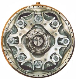
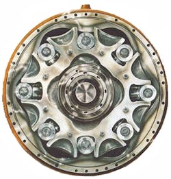
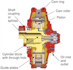
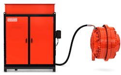
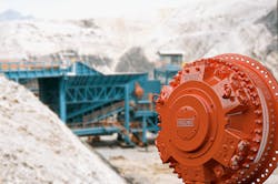
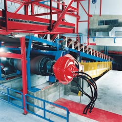
Large hydraulic direct drive systems for low-speed, high-torque operation typically consist of a hydraulic radial piston motor and a hydraulic power unit (Fig. 1). The hydraulic radial piston motor is a hydraulically balanced radial piston cam curve unit. It is connected directly to the driven shaft. Pressurized hydraulic fluid is fed into the cam chambers. The fluid moves the pistons, which are mounted around the drive shaft in a radial direction, rotating the drive shaft. The radial piston motor has a high efficiency rate (close to 97%) approaching the energy transfer efficiency of a roller bearing.
The radial piston motor is a fixed displacement and bi-directional unit, able to change rotation direction and speed with simple command control. Its typical operating range offers torque up to 2,000 kNm and a rotational speed up to 550 RPMs. Most importantly, this design delivers constant torque throughout the speed range, and unlimited starts and stops with the high torque demanded at each restart.
As part of the motor frame, it can be flange mounted or torque arm mounted to take out reaction force while eliminating undesirable forces on the motor bearings. This is accomplished by positioning the flange or torque arm in relation to the load being driven. The pivot attachment allows the motor to follow shaft deflection with three degrees of freedom without overloading motor bearings.
The hydraulic power unit supplying the radial piston motor consists of a fixed-speed electric motor driving a variable displacement axial piston pump, a pump controller, a fluid monitoring system, and a hydraulic fluid reservoir. The power unit connects to the radial piston motor via cabling and hydraulic hoses; this has the advantage of enabling system designers to position the pump, electric motor, and controllers in an enclosure away from the operational axis for greater design flexibility and to protect these components (particularly electronics) from harsh operating conditions.
This file type includes high resolution graphics and schematics when applicable.
Key Direct Drive Advantages
This file type includes high resolution graphics and schematics when applicable.
Hydraulic direct drive technology of radial pistons has been adopted in many environments, but advances in the technology—smaller size and weight, along with the ability to offer the highest power density and high torque at low speeds—makes this a viable option for an expanding range of applications and environments.
In particular, hydraulic direct drives offer a particularly effective alternative (or even retrofit replacement) for electromechanical drive options, for the following reasons:
- Power density: Almost all the energy of the hydraulic system transfers to the axis of rotation to perform the work. This makes it well-suited for conveying and transport systems that don’t require high RPMs to turn the axis of motion, but do require high torque.
- Energy efficiency: There is no need for bedplates, couplings, or gear reducers between the motor and the driven shaft. As there are no high-speed elements which need speed reduction, the hydraulic motor can develop its exceptionally high torque from zero to full speed. This allows excellent controllability of the feeder speed for all material conditions.
- High torque on demand: The system supplies a high torque in the range of 2,000 kNm at start-up and allows, through changes in the pump output, changes in the speed and torque being supplied as needed for the given load cycle instantly.
- Reliable start and stop operation: The system does not undergo shocks when restarting and has a smooth power curve from a soft start, thus minimizing impact on the equipment being driven (e.g., belts on conveyors).
- Designed for operation: Compared to electromechanical systems with gear reduction, hydraulic direct drives have fewer parts to undergo wear and tear; this helps maximize equipment uptime, eases maintenance requirements, and makes these systems more reliable and able to deliver higher levels of uptime, particularly in rugged operating environments.
While widely used, it has been shown that complex gear reduction systems used in other drive platforms demand higher levels of maintenance, parts replacement and, in many applications which undergo shock loading, higher rates of failure and replacement than many operators would prefer. With shock loading, the repeated and sudden variations in load (unavoidable in applications as diverse as mining, power plants, and scrap metal movement) cause the variation in load to be transferred back through, and physically impact, gearing and other components.
In a hydraulic direct drive system the hydraulic fluid acts as a spring, much more efficiently absorbing the load variation without transferring the mechanical energy to the motor or pump components. In addition, gear reduction actually wastes power in low-speed high-torque operating conditions, rather than maximizing the power density of the drive system.
Key Usage Considerations
As system designers assess the drive technology to be used for high-volume, heavy-duty transport systems, there are several additional considerations to take into account when evaluating the potential of hydraulic direct drives:
- Four-quadrant operation: The four quadrant operation means the motor can provide both driving and braking action in both directions. Radial piston motors can change rotation direction through a simple controller signal, then switch back to their original direction without impact overall system performance.
- Compact power: The newest hydraulic direct drives now being offered combine smaller sizes and lighter weight with much higher power density. This enables more options for implementation in a wider range of applications. They can fit into tighter machine locations and be mounted directly on the main drive axis of a bucket wheel excavator without adding significant excess machine mass or weight.
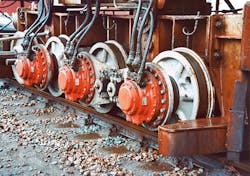
- Tandem systems: For applications requiring higher torque than a single radial piston motor can offer, two or more hydraulic motors can be mounted in a tandem configuration, with a single hydraulic power unit configured to support the multiple motors. This can be two motors driving a single axis or, alternately, four motors driving two axis (at both ends of a conveyor, for example); this is an easier way to ensure that both motors carry a common load, since the hydraulics are all part of the same closed loop circuit sharing the load naturally. It also multiples the power advantage of hydraulic direct drives. One example of a solution combines four direct drive motors powering multiple pulleys to create a 5,000 hp conveyor drive.
- Retrofit solutions: For existing facilities that seek to capture some of the benefits associated with hydraulic direct drive systems, minimal re-configuration is required to replace electromechanical drives with hydraulic direct drives. Particularly for large-scale resource and bulk material handling operations that can experience significant losses due to a gearbox failure, hydraulic direct drives can be married with existing conveyor axis or other equipment in comparatively short timeframes.
-
Total cost of ownership: Although electromechanical solutions may have a lower initial cost of ownership, there are some lifecycle factors that system designers and end-user operators should consider when assessing the potential for hydraulic direct drives:
- High reliability of hydraulic direct drives due to low moment of inertia and high shock load resistance. This practically eliminates the need for coupling alignment, and there is no risk of gearbox failure with hydraulic direct drives.
- Space savings and weight savings with many indirect cost savings.
- Cost of electricity. Using DC or VFD high-speed electric motors and over-dimensioned gear boxes can require more energy to operate over a wide range of speed and various load capacities compared to hydraulic direct drives. These do not require over-dimensioning, and the modular sizing of electric motor and pump combinations allows more flexibility to optimize this.
- Wear and tear on gearbox equipment can increase repair and replacement costs, potentially leading to a shorter operational lifetime compared to hydraulic motors (many gearboxes fail prematurely and contribute costs associated with production downtime).
Hydraulic Direct Drives: Efficient and Effective
It can be seen that there are significant advantages to utilizing hydraulic direct drives for a growing range of applications. Currently, hydraulic system providers offer a range of direct drive hydraulic motors, typically rated by their RPM capacity and torque capacity; they range from 2,000 Nm to 2 million Nm (the higher the torque, the lower the maximum RPM speed).
Selecting and configuring a hydraulic direct drive system is based on the load and speed demands of a given application. Calculations to be considered include:
- Torque range required, both the starting values and operating values
- The RPM required for the system’s driven shaft
- Total duty cycle–loads, frequency of start/stop conditions, potential peak shock loads
These factors also govern the size of the fixed displacement motor, hydraulic fluid reservoir, and electric drive that will be chosen.
Hydraulic direct drive systems offer a rugged, proven option for low-speed high-torque applications. By being able to do more with less; they are highly efficient, while providing high power densities. Simpler and more reliable compared to electromechanical drive systems with gear reduction, hydraulic direct drive systems demonstrate a viable, cost-effective, long-term option for many of the most demanding transport and material handling requirements.
Ashok Amin is Mining & Material Handling Segment Manager, North America for Bosch Rexroth Corporation.
This file type includes high resolution graphics and schematics when applicable.
