How bolt patterns react to external loads
|
Authored by: |
In a bolted joint, all the bolts react against external loads, but they rarely share those loads equally. So to correctly size bolts for a joint, engineers must determine the maximum bolt reaction in a worst-case scenario.
This file type includes high resolution graphics and schematics when applicable.
The essential properties of a bolt pattern are its elastic center and reaction module. The principal elastic axis is the out-of-plane axis in which external forces acting on it do not tilt the support plane. And the bolt pattern’s elastic center is the intersection of the principal elastic axis and plane of the bolt pattern. The coordinates of the elastic center are the stiffness-weighted averages of all bolts’ coordinates. Engineers can determine the X and Y coordinates of the elastic center using:
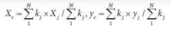
Note that if all bolts have the same stiffness, the elastic center coincides with the centroid.
Coordinates for the mass center or center of gravity (CG) are the mass-weighted averages of all mass points’ coordinates.
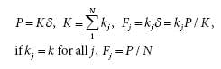
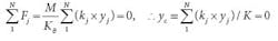
Both the pull-out force and rocking moment generate tension in bolts. A pull-out force on the elastic center stretches all bolts uniformly by ð = P/K and each bolt’s share of the reaction is proportional to its stiffness. Therefore, the stiffer bolt shoulders a larger share of the overall reaction to pull-out force on elastic center:
A pull-out force off the elastic center can be replaced by a force of the same magnitude at the elastic center and
a moment. Then bolts are subject to force, P, and induced moment M = eP. As a result, the reaction would be larger than P/N for some bolts. To prevent this, reduce eccentricity, e, by putting the elastic center under P or bringing CG toward the elastic center.
An external moment rotates the entire bolt pattern by α = M/Kθ as if it is on a rigid plate. The external moment and reaction moment are in equilibrium.
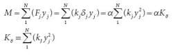
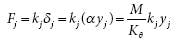
The reaction force at each node becomes:
There is no external force on the pattern, so the sum of reaction forces is zero. That makes Yc = 0 and the reaction moment axis must pass through the elastic center.
Consequently, the reaction of the entire bolt pattern may be treated as if the external moment were on the elastic center (shown as Mc) regardless of the actual load positions at M or M1. The same argument holds for a moment on the Y axis. Generally, ri represents moment arms for rotation in X, Y, or any skewed axis, and the maximum reaction force becomes:
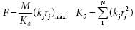
If all bolts have the same stiffness, the rotational stiffness becomes the moment of inertia and the bolt farthest from the elastic center bears the largest share of the reaction to the moment:
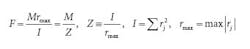
The reaction module, Z, is a property of the bolt pattern that relates the maximum reaction and moment load. A sure way to reduce the maximum bolt reaction is to increase the reaction module. The reaction module of the bolt pattern is akin to the section module of a beam used for computing the bending stress from a moment.
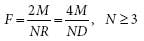
A uniform circular bolt pattern has equally spaced bolts. Calculate the reaction module Z = Ix/rmax for a circular pattern using:
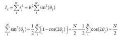
It can be shown that [2θj, j = 1,..N] are equally spaced on the unit circle (R = 1). Therefore, their centroid is at the origin and ∑ cos(2θj)/N is its X-axis coordinate. Consequently,∑ cos(2θj) = 0.By substituting ( θj + θ ) for j in the equation for inertia, the same argument leads to inertia invariance, Iθ = Ix= NR2 2 for any axis skewed by θ . The largest rj may be less than R for some patterns and coordinate setups. But for a moment arm laid on the radial link to a bolt node, there is an associated rotation axis perpendicular to that link. Every axis so constructed is a critical axis because rmax = R, and I =Ix , based on inertia invariant theory. Therefore, Z = I/rmax = Ix /R = NR/2. Finally, the working formula for reaction force of a circular pattern F = M/Z is:
The least restrictive, N, is helpful. Engineers use three points to define a plane and prime numbers to avoid resonance. So eliminating just one bolt can cut costs and may save fuel in mobile and aerospace equipment.
Equilateral triangular and square patterns are circular patterns with N = 3 and N = 4, respectively. As the number of bolts approaches infinity, the circular bolt pattern becomes a ring. For a ring, I = π R3, Z = π R2, and f = M/π R2. The reaction module of a ring, π R2, should not be confused with the circular area because the two have different physical meanings. Ring-pattern equations can be used for stress analysis of circumferential fillet welds of a cylinder to a base and soldering wires on a circuit board.
Rectangular four-bolt pattern reactions to moments in the “limber” (Y) axis and “stiffer” (X) axis, respectively are:
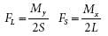
In typical format Iy = 4a2, rmax = a, Zy = Iy /rmax = 4a = 2S and FL=My/ Zy. (The terms “limber” and “stiffer” axis are adopted from J. P. Den Hartog, Strength of Materials, Dover, 1949, p. 115).
The maximum reaction upon a moment on an axis skewed by is:

If the moment acts at a skewed angle, θ , the critical angle in a worst-case scenario is found at the zero derivative dF/d θ = 0. This condition leads to the diagonal.
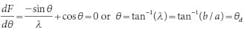
The maximum reaction then becomes:
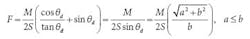
For a square pattern, F = √ 2(M/2S). Widening the footprint to form a rectangular pattern decreases the multiplier from √ 2 to 1/sinθ, but overextending the limber axis of a rectangle yields diminishing returns in terms of reducing reaction.
A rectangular pattern with onebolt- missing becomes a right-triangular pattern. Even though the external moment remains on the centroid of the rectangle noted as M’, the reaction moment is on the new elastic center of the remaining three bolts. The centroid of the three remaining bolts shifts away from the centroid of the rectangular pattern by Δx = a/3, Δy = –b/3. The moments of inertia and the reaction modulus are Iš = (8b2/3), I = (8a2/3), Z = 2b, Z = 2a. These reaction modules are half the value of those for the original rectangular pattern with all four bolts active. Therefore, reaction loads double under the one-bolt-missing condition for a moment load.
Similar to the rectangular pattern, the critical axis for maximum reaction of the one-bolt-missing pattern in a worst-case scenario is on the diagonal of the rectangle and the bolt reaction is twice the value of that for the rectangular pattern.

Under the one-bolt-missing condition, pull-out force on the centroid of the rectangle becomes an off-center force on the right-triangle pattern. (The “One-bolt-missing pattern” table shows the effects of both pull-out force and induced moment.) The maximum reaction increases from P/4 for all four bolts active to 5P/12 after losing one bolt.
It is interesting to note that by losing one bolt, the reactions on pull-out force and moment increase by 5/3 and twofold, respectively, for all sizes and shapes of rectangular patterns. The one-bolt-missing condition does not necessarily require one bolt being physically absent. Completely losing preload on one bolt would establish the same condition.
The uniformity of some patterns is seen in a simplysupported beam model in which the reaction force is F = M/W where the support span, W, is the reaction module.
In summary, elastic center and reaction module are key properties of bolt patterns. The reaction-moment axis passes through the elastic center. The circular-pattern reaction formula applies to all bolt numbers larger than two. The critical axis of moment on a rectangular pattern is on a diagonal. One bolt missing from a rectangular pattern increases reactions to pull-out force by 5/3 and increases the reaction to moment load by a factor of two.
Going beyond the numbers
Here are some best practices engineers follow when designing bolted joint:
Identify the major loads that dictate the supporting scheme. Secure sufficient reaction modules early. Choose symmetric or axisymmetric bolt patterns when possible. Update the assembly’s center of gravity and elastic center of support as often as needed. Align the center of gravity with the elastic center, or at least reduce eccentricity to a minimum. And reduce the angular noise driver, M = emG. Angular noise is the angular response without angular input that rocks the machinery or contaminates instrument signals.
Keep all bolt stiffness in a joint approximately the same. Use bolts of the same size and same effective lengths. Select compatible thickness and material for clamped members, including sleeves, washers, threaded inserts and mounting lugs. It is better to use all through-bolts or all studs rather than mixing the two. Avoid straddling a bolt connection over structures with uneven flexibility.
Make sure the bolts can be preloaded. Use friction between clamped members to resist shear load. If a conventional structural joint slips, no more than two bolts in a cluster should be counted on to resist shear load. The first bolt stops sliding while the second stops rotation of members. Shear bolts such as shaft coupling bolts demand more stringent dimension tolerances and handling than tension bolts.
Avoid bending load on bolts. Stay away from single bolts, and single and double-row bolts located close together. The latter may form a couple with huge tension to react a moment. Do not make bolts serve double duty.
Do not use a bolted joint for accurate alignment. Be clear on which facet of which part controls alignment, then let everything else in the assembly float. Use discretion in moving a bolt from its symmetric pattern location for matching orientation of mating parts. Don’t use high-pressure boundary joints as structural supports or vice versa. Don’t mess with pressure boundaries.
