Engineering Essentials: What Is a Programmable Logic Controller?
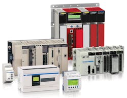
A programmable logic controller (PLC) is an industrial solid-state computer that monitors inputs and outputs, and makes logic-based decisions for automated processes or machines.
PLCs were introduced in the late 1960s by inventor Richard Morley to provide the same functions as relay logic systems. Relay systems at the time tended to fail and create delays. Technicians then had to troubleshoot an entire wall of relays to fix the problem.
PLCs are robust and can survive harsh conditions including severe heat, cold, dust, and extreme moisture. Their programming language is easily understood, so they can be programmed without much difficulty. PLCs are modular so they can be plugged into various setups. Relays switching under load can cause undesired arcing between contacts. Arcing generates high temperatures that weld contacts shut and cause degradation of the contacts in the relays, resulting in device failure. Replacing relays with PLCs helps prevent overheating of contacts.
PLCs do have disadvantages. They do not perform well when handling complex data. When dealing with data that requires C++ or Visual Basic, computers are the controllers of choice. PLCs also cannot display data well, so external monitors are often required.
PLC Hardware Components
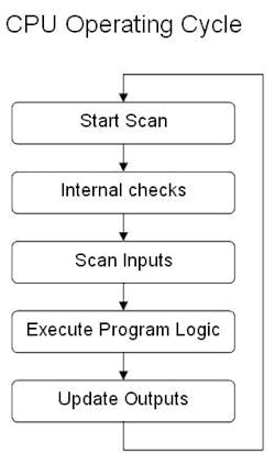
A central processing unit (CPU) serves as the brain of the PLC. It is a -16 or -32 bit microprocessor consisting of a memory chip and integrated circuits for control logic, monitoring, and communicating. The CPU directs the PLC to execute control instructions, communicate with other devices, carry out logic and arithmetic operations, and perform internal diagnostics. The CPU runs memory routines, constantly checking the PLC (PLC controller is redundant) to avoid programming errors and ensure the memory is undamaged.
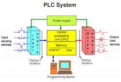
Memory provides permanent storage to the operating system for data used by the CPU. The system’s read-only memory (ROM) stores data permanently for the operating system random access memory (RAM) stores status information for input and output devices, along with values for timers, counters, and internal devices. PLCs require a programming device, either a computer or console, to upload data onto the CPU.
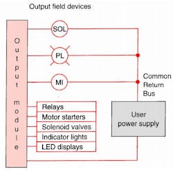
PLCs read signals from different sensors and input devices. These input devices can be keyboards, switches, or sensors. Inputs can be either in digital or analog form. Robots and visual systems are intelligent devices that can send signals to PLC input modules. Output devices such as motors and solenoid valves complete the automated system.
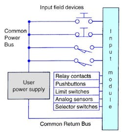
Direct current (dc) input modules connect to sourcing or sinking transistor type devices. Alternating current (ac) input modules are less common than dc inputs because most sensors have transistor outputs, so if the system uses a sensor input, it will most likely be dc; ac inputs take longer for PLCs to see compared to dc inputs. A typical ac input is a mechanical switch used for slow mechanical drives.
Relays are one of the most common output connections. A relay can switch ac or dc modules because they are non-polarized. A relay is slow, switching and settling at speeds of 5 to 50 milliseconds (ms), but can switch a large current. For example, a relay can be used for a low-voltage battery to switch a 230 volt AC main circuit. Transistor connections are faster than a relay and have a long lifespan. Transistors switch a small current, but only work with dc. An example of a high-power transistor has a current of 15 amps with a max voltage of 60V. Triac output (triode for alternating current) connections only control ac loads. Like a transistor, a triac is faster and handles large ac loads. A triac output, for example, can handle voltages of 500 to 800 with a current of 12 amps.
PLC Programming Language
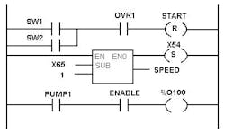
Five programming languages are used in PLCs. They are defined by the international standard IEC 61131. Ladder logic is one of the most commonly used PLC languages. In it, symbols represent opening and closing relays, counters, timers, shift registers, and mathematical operations. The symbols are arranged into the desired program routine. Rules in ladder logic are termed “rungs.” Each rung has a single output, but a single input can be found in more than one rung.
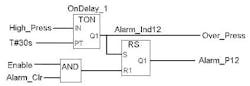
Another programming language is function block diagram (FBD). It describes functions between input and output variables. The function, represented by blocks, connects input and output variables. FBD is useful in depicting algorithms and logic from interconnected controls systems.
Structured Text (ST) is a high-level language that uses sentence commands. In ST, programmers can use “if/then/else,” “SQRT,” or “repeat/until” statements to create programs.
Instruction list (IL) is a low-level language with functions and variables defined by a simple list. Program control is done by jump instructions and sub-routines with optional parameters
Sequential Function Chart (SFC) language is a method of programming complex control systems. It uses basic building blocks that run their own sub-routines. Program files are written in other programming languages. SFC divides large and complicated programming tasks into smaller and more manageable tasks.
PLC Communications
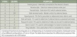
RS-232 is the most common method PLCs use to communicate with external devices. It is a serial communication standard that uses binary code to transmit data in American Standard Code of Information Interchange (ASCII) format. ASCII translates letters and numbers into binary code that computers can read. ASCII is a 7-bit code (a bit being “1” or “0”) that, when translated, results in 128 characters. PLC serial ports transmit and receive data as voltages. PLCs can be either data terminal equipment (DTE) or data communications equipment (DCE). A DTE, for example, can be a computer, while a modem is a DCE. Typically, PLCs are DTEs and external devices are DCEs. When the PLC and the external device connected to it are the same equipment (i.e., DTE/DTE or DCE/DCE), they cannot communicate with each other and a null-modem connection must be used.
In serial communications, data gets transmitted one bit at time. Data is separated into its constituent bits for transmission and reassembled when received by an external device. A “start bit” is the initial signal sent and precedes any other communication bits. It is considered the “space” or negative voltage. The “stop bit,” the last code sent, is considered a “Mark” or a positive voltage.
Eight bits make a byte and PLCs are byte-oriented. ASCII is a seven-bit code, so the eighth (or “parity byte”) checks to see if data has been corrupted. Common forms of parity include even (1), or odd (0). The total number of 1s in the byte adds up to an even or odd number. The sending equipment determines if the communication is even or odd and receiving equipment compares the result of the parity to the eighth bit to ensure they match. If a device transmits 1001101 and computes it to be an odd value, it will add a 1 to the eighth bit and send 10011011. The receiver decides the bit is odd and verifies an odd total of 1 characters.
Baud rate is the number of bits per second transmitted from DTE to DCE. An RS232 transmission would appear as baud rate, data bits, and parity-stop bits. For example, the string 9600-8-1-1 translates to a 9600 baud rate, 8 data bits, a 1 for parity, and a 1 stop bit to end the transmission.
Software handshaking ensures devices are ready to send and receive data. The receiver sends the XOFF character when it wants the transmitter to pause sending data. It sends the XON character when it is ready to receive data again. XOFF is sometimes referred to as the hold-off character and XON as the release character.
A delimiter is added to the end of messages to tell receivers to process the data just received. The most common delimiter is the “carriage return” (CR). The PLC or external device receives the delimiter and takes data from its buffer. The buffer temporarily stores data before it is processed. The line feed (LF) is sometimes sent with the CR character. If viewed on a computer, the page moves down a line to start a new line of communication.
PLC Selection Criteria

There are several requirements to keep in mind when choosing PLCs. Is the proposed system new or an existing one? Either way, ensure the controller works with mating hardware.
Environmental conditions will affect PLC performance. Typical controllers operate in temperatures from 0 to 55°C (32°-130°F). The number of discrete devices (On/Off logic devices) and analog devices determines the number of I/O connections the PLC will need. If the discrete devices are ac or dc, determine if the PLC can support the required signal.
Determining CPU requirements is important for calculating the amount of RAM needed for data manipulation and storage. Counters and timers use RAM to store set points, current values, and other internal flags. If data must be stored over a long period of time, CPU memory must be sized appropriately.
Program memory or ROM stores program instructions. Analog devices usually require 25 words of memory per device. Examples of analog devices are voltage, current, and temperature meters or sensors. Simple and sequential applications typically require five words of memory per I/O device. Complex applications are not as predictable and need more program memory space.
Serial and Ethernet connection-based I/O hardware are typical choices for remote connections. Remote devices are needed when the PLC is located separately. Serial connections have a max distance of 50 feet while Ethernet connections can go to a max of 328 feet. These remote devices are referred to as distributed I/O. Finally, be sure the PLC understands program instructions. Some PLCs come with proportional integral derivative functions that eliminate the need for technicians to write specific code for closed-loop process control.
