FEA Exercise: How to Analyze a Simple Dynamic Load
This file type includes high resolution graphics and schematics when applicable.
Often, technical analysis forces engineers to find missing pieces of information before they can proceed with design improvements. That was the case in a recent job where we were asked to help design a container from steel for encasing low-level radioactive waste (LLRW).
Such waste consists of items such as gloves, personal protective clothing, tools, water-purification filters, and plant hardware such as pumps and valves that have come in contact with radioactive materials. LLRW generally has levels of radioactivity that decay to background radioactivity levels in less than 500 years.
To dispose of LLRW, operators put the waste into steel vessels and fill the remaining vessel volumes with concrete. Operators then set the vessels aside until the concrete cures. Then they go into permanent burial.
At the LLRW facility we helped, LLRW material mixes with wet concrete while the container sits on a forklift. The concrete completely fills the container. Then the forklift moves the containers from the filling station to a temporary curing station on the ground. But before the redesign, even though the placement onto ground was slow — 3 in./sec — it caused a significant impulse that excited a vibration mode and sloshed the uncured concrete-and-waste mix.
When we were asked to address the problem, we didn’t know the bulk modulus of curing concrete mixed with unknown debris. Therefore, we took a common course of action and bounded the data with worst-case and best-case values. Then we got data for the concrete slurry from a pump manufacturer and used this as a starting point for more calculations. Additional runs at various values yielded the most probable (and conservative) bulk-modulus value that made physical sense.
Waste-container application specifics
In our application, when the forklift sets the filled vessel down, the dynamic load is a 30 × 40 × 80 in. box made of 11-gage sheet steel with a circular opening on top. The vessels have two 18.7 lbm/ft “C” channels for the forklift arms to engage. These channels span the container’s opening and let operators stack the containers one on top another.
The container can’t bulge or yield when it’s being filled with wet concrete. Nor can it deform when the forklift moves it to sit and cure.
Only after curing is the container is a solid brick of concrete that can go to a permanent-storage facility.
Analysis method
We analyzed the application’s dynamic loading with finite element analysis (FEA) in commercially available software. We modeled geometry, strike duration, and material properties.
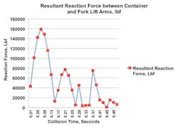
Here is the reaction load approaching the 10,500-lbm static container weight after approximately 0.5 sec after contacting the ground:
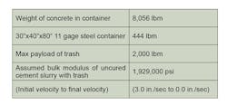
Key to the design was picking a value to use for the bulk modulus of wet, uncured concrete when mixed with disparate nuclear-waste debris. These are the key design values that we ultimately picked based on calculations:
This file type includes high resolution graphics and schematics when applicable.
Minimizing deflection
This file type includes high resolution graphics and schematics when applicable.
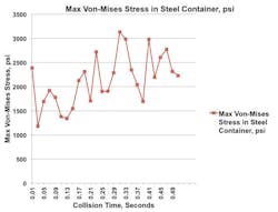
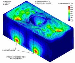
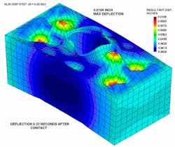
Thanks to the addition of 2 × 2 × 1/8-in. angle corner braces, stress levels in the 11-gage steel vessel stayed below 3,135 psi — an acceptable level. What’s more, deflection levels stayed between 0.009 and 0.031 in. over the entire slow-collision event — also acceptable levels. Most of the deformation was due to the wet concrete sloshing in waves under the sheet metal skin.
We observed three other things when working on this design.
1. As with many engineered systems, cost was a major consideration in this project.
Because LLNW sites use dozens or even hundreds of containers to encapsulate large volumes of waste, overdesigning the steel vessels wastes money. What’s more, the steel doesn't provide any function after the concrete cures — as the concrete becomes a brick that’s structurally stable for 500 years regardless of the steel’s condition.
2. Overdesigned parts are usually unnecessary, because simple solutions often work best.
We wanted to make the shell’s stress distribution even as possible. So, we added steel angle braces to its corners. That reduced stress concentration at the corners. In fact, a plot of the modified steel container’s stress 0.11 sec after contacting ground shows no corner stress gradients:
3. Engineers should evaluate the results of any analysis. To do this, engineers should ask: Does the analysis make physical sense? In the application we profile here, the concrete seems to pull and push correctly on the walls. It also makes sense that the static vertical gradient stress is far smaller than the dynamic stresses.
Fred Jensen is the Director of Engineering of Patriot Engineering Co., Chagrin Falls, Ohio.
This file type includes high resolution graphics and schematics when applicable.
