New ways to damp vibration on linear axes
When in doubt, make it stout. That was the rule of thumb for designing strong and durable machine tools in the past. Over the years, however, this mindset has changed as technical advances have allowed for dramatic increases in the performance of machine tools within the same design envelope. Better modeling software and analysis tools, along with advancements in radial and linear bearings, have increased machine spindle and traverse speeds. At the same time, motor, drive, and position-feedback capabilities compensate for mechanical inaccuracies. All of these developments have fostered faster, more-precise machining.
Nevertheless, the never-ending demand for higher speeds, deeper cuts, and better accuracy to increase throughput continues to challenge engineers designing the next generation of high-performance machine tools. Focusing on dynamic stability through effective axis damping may be the key to meeting these challenges.
Linear-guide characteristics
As designers continue to push the envelope even further in pursuit of greater throughput, some of the advances that contribute to higher speed also present certain drawbacks. The evolution from plain bearings to ball and roller-recirculating linear guides is one example.
Plain-bearing systems, while inefficient and limited in speed, have very good damping characteristics as a result of their large surface-contact areas and lubrication film. The effect of this inherent damping lets machinists increase the cutting depth while maintaining good surface finishes and accuracy. Many CNC lathes built today still use plain-bearing slides on their turret axis because of these advantages.
On the other hand, while ball and roller-recirculating linear guides have low coefficients of friction and high speed ratings, they offer poor damping characteristics because of the metal-to-metal point and line contacts of their ball or roller elements transitioning between the steel bearing body and rail.
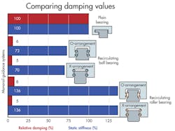
The nearby chart, Comparing damping values, shows the relationship of stiffness versus damping in plain bearings and recirculating-type bearing guides. Using a plain bearing system as the baseline, results show similar rigidity values for all the systems. But when it comes to relative damping values, there is a significant difference.
Structural dynamic rigidity
Some designers make the mistake of focusing mainly on a machine’s static rigidity. In actuality, it is also important to consider the balance of the overall structural mass with highly preloaded linear bearings for increased static rigidity, versus lower structural inertias for increasing chip-to-chip speeds. Properly balancing rigidity and inertia increases machine dynamics which, in turn, boost overall machine performance. High dynamics has a significant influence on the machine’s structure and its elements. Vibrations induced by cutting-tool pass frequencies and wear, along with other outside disruptive forces, can cause poor machine performance. Dynamic rigidity through proper damping can reduce these influences.
Modeling a three-axis machine that uses recirculating linear bearings and guide rails shows the interaction of damping and rigidity. In the nearby graphic, c represents rigidity and d represents damping values of the linear bearings. Force, F, is applied to the spindle nose and δ is the elastic response.
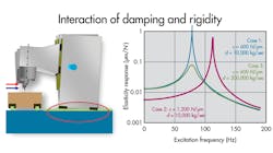
In case 1, the model has a rigidity value of 600 N/µm and a damping value of 10,000 kg/sec. The results show a modal peak around 80 Hz. In case 2, rigidity is doubled to 1,200 N/µm and damping remains the same. Here, results show the mode shifts, but the amplitude is almost the same. For case 3, the rigidity value matches case 1, but the damping input increases to 200,000 kg/sec. The result is now a modal peak similar to case 1, but at a much lower amplitude. This validates that rigidity cannot replace a lack of damping.
Integrating linear-axis damping
Two effective methods for adding damping to the linear axes are known to designers yet, surprisingly, they are seldom used. These methods involve the use of adaptive elements or complete hydrostatic systems.
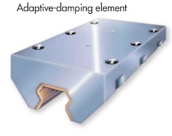
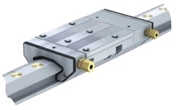
The adaptive method integrates a damping element within the recirculating linear guide. The damping element, or carriage, fits on the same linear-guide rail and has an inner profile that matches, but does not contact, the rail. The gap between the damping carriage and rail is approximately 25 µm (0.001 in.). This gap is filled with oil using a gravity drip feed through ports in the carriage. The squeeze-film effect provides damping similar to that of a shock absorber on a car. Because the gap is very small, capillary action maintains the oil film, and there is minimal fluid loss during linear cycling of the slide provided that the unit contains proper-viscosity oil. The length of the damping carriage directly influences the magnitude of damping. Because flat surfaces are preferred for this method, only roller-type guide rails are used.
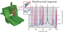
The FEA model labeled Machine-tool response shows the modal frequency response of a vertical-machining center at the spindle nose using roller profile rails. The first modal response curve (in red) is based on a linear-rail system that uses only roller guide bearings on the Y and Z axes. The second response curve (in blue) shows results after implementing damping carriages between the roller guide bearings on the Y and Z axes. Results reveal a significant reduction in the amplitude of the modal frequencies generated by cutting forces at various feed rates and spindle speeds. This, in turn, permits greater cutting depths at higher speeds and, consequently, better machine performance.
Hydrostatics
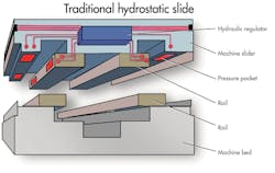
The other method for integrating linear-axis damping is through complete linear hydrostatic-bearing systems. While this is not a new concept, the economics have not justified widespread adaptation. These types of systems have pressurized hydraulic cavities or pockets within the axis table. What makes this design so costly is that it requires a series of cross-drilled passages and ports that have to be generated with extreme accuracy.
Another drawback of hydrostatics is the challenge of sealing and controlling bypass leakage of high-pressure fluid. Most of these designs are open-type loss systems which must contain fluid-collection troughs. Fluid that leaks past the bearing has to be collected and filtered before reuse.
Finally, these systems always face the nightmare scenario where failure means the complete slide assembly must be repaired or replaced.
New options
The drive to produce a more cost-effective alternative has led to the development of next-generation hydrostatic linear systems, which can be engineered into a machine in much the same way as current linear-recirculating guides.
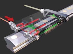
These compact hydrostatic guides operate as a closed-loop unit. Carriages with pressure pockets ride on precisely honed guideways energized by a steady layer of pressurized oil. The hydrostatic guide carries loads on these oil-filled pressure pockets.
The carriage consists of a steel saddle plate and two end pieces. One end piece has an integrated pressure regulator that supplies oil to the carriage’s pressure pockets. The other, a suction-side end piece, extracts depressurized oil and sends it back through the oil circuit.
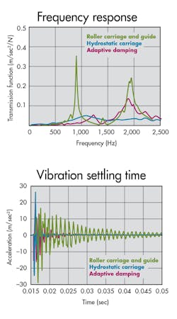
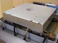
To prove the effectiveness of this type of hydrostatic guide, we tested three different slide assemblies, one at a time, installed in a motion table. The first configuration used standard Size 45 roller carriages and guides; the second slide included damping carriages between the roller guides; and the third used hydrostatic carriages and guides.
For each setup, we applied a controlled impact force at the center of the table and measured the vibration response using an accelerometer. Results show modal response and settling times from this impact. With the standard roller system serving as the baseline, the additional damping carriage significantly reduced dynamic response. But the hydrostatic system achieved the best result, virtually eliminating the dynamic response.
The advantage of the hydrostatic carriage and rail is that it fits into the same design space, with the same mounting-hole locations, as standard linear guides. Thus, engineers can spec them into machines with minimal design effort. An OEM can now offer machines using standard linear guides, with adaptive damping carriages, or with upgrades to complete hydrostatics on the same machine platform, depending on customer requirements. New designs can focus on reducing structural mass for higher accelerations and traverse speeds.
Currently, hydrostatic carriage and rail systems cost about four to five times as much as conventional roller profile-rail systems. But like anything else, as market demand increases production volume, costs will come down. Key to driving this demand will be competition between manufacturers seeking to offer their customers a technological edge in machine-tool performance.
Carl White, Manager – Application Engineering, Linear and Production Machinery, Schaeffler Group USA, Fort Mill, S. C.
Edited by Kenneth J. Korane, [email protected]
Resources: Schaeffler Group USA, www.schaeffler.us
