Analyzing the essentials of bearing performance
|
Authored by |
The rolling elements in antifriction bearings are critical components that can affect the overall performance of an entire machine. Engineers must consider their many attributes to get the best bearing performance, including: • Diameter and diameter tolerance. • Axial profile. • Radial clearance. • Surface finish.
In many cases, catalog data alone does not provide enough information for engineers to confidently specify a bearing and predict performance — particularly in critical applications. Fortunately, some major bearing manufacturers offer application-analysis services that delve deeper into design and operating details. Such analysis considers all bearing inputs and recommends designs or products that deliver the required performance.
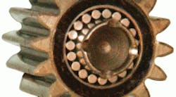
As an example, let’s look at some gearbox bearings that recently came under the scrutiny of RBC Bearings, Oxford, Conn. These bearings support a helical gear in a simple planetary set, using two rows of loose needle rollers housed in the bore of the gear, as shown in the accompanying graphic. Shaft OD is approximately 0.500 in. and gear bore is about 0.750 in. The unit runs at a maximum speed of 2,300 rpm.
Among the areas analyzed:
• Loads on the bearing and individual needle rollers.
• Contact pressure on the most highly stressed rollers.
• Subsurface stress in the raceway, and how it compares to the strength of the raceway material.
A free-body diagram shows tooth-separating forces, S, which are equal and opposite and, therefore, do not add to the load on the bearing. The tangential tooth forces, F, act in the same direction and are additive. Equal and opposite thrust tooth forces, T, add no net force on the bearing, either. However the thrust tooth forces do create a moment with a magnitude of 2T multiplied by the gear’s pitch radius. The needle rollers react to the applied forces and moments which, in this case, are –4,033 lb of load and –860 lb-in. of moment.
Applying this load and moment to the bearing in the company’s simulation program gives loads on rollers in positions 1 through 6 and 13 through 17, (shown in the “Roller position loads” illustration). Roller position 1 bears the greatest load. However, positions 3 and 6 are the most heavily stressed roller positions due to reactions to the overturning moment.
The “Individual roller loads” graphic shows a top view of the two roller paths, depicting the magnitude and distribution of the load on each roller. The numbers between the roller paths indicate loads on each roller. Although rollers 2 and 17 have the highest loads, rollers 3 and 16 have the highest concentration of load (the widest red area) and, therefore, the highest stress due to misalignment caused by the overturning moment.
Using a program coded specifically for this type of analysis, application engineers can then analyze the contact pressure with the raceway on roller positions 3 and 16. A “Contact pressure” plot shows three details: the effective length of the roller is along the horizontal axis; the width of the contact patch along the axis going into the page; and the contact pressure on the vertical axis. Contact pressure is skewed due to the skewed loading pattern on the roller, and it exceeds 500,000 psi — which is considered quite high.
The last graphic plots subsurface stress versus material strength. The red line represents the subsurface von Mises effective stress due to contact pressure; the blue and purple lines show the yield and tensile strength, respectively. Here, the von Mises subsurface stress in the material slightly exceeds the yield strength of the case-hardened material. Therefore, the material needs to be replaced or the heattreatment process changed to improve performance.
These results give just a few examples of the types of analysis available to help improve bearing applications. Other analyses might recommend:
• Bearing size, number of rollers, limiting speed, misalignment capability, and the axial profile required on the races and rollers.
• Shaft, housing, and gear bore sizes, materials, surfaces finishes, and hardness.
• Lubrication requirements.
• Materials and heat treatment required on raceways and shafts.
These and other guidelines let OEM designers specify bearings that precisely match intended performance and life requirements.
About the Author
Kenneth Korane
Ken Korane holds a B.S. Mechanical Engineering from The Ohio State University. In addition to serving as an editor at Machine Design until August 2015, his prior work experience includes product engineer at Parker Hannifin Corp. and mechanical design engineer at Euclid Inc.
Voice Your Opinion!
To join the conversation, and become an exclusive member of Machine Design, create an account today!

Leaders relevant to this article: