Telecentric Illumination for Vision-System Backlighting
Authored by: Edited by Leland Teschler Key points: • In a telecentric lens, the rays which pass through the center of the aperture are parallel to the optical axis in front of or behind the system. •Backlighting via telecentric lenses can eliminate the problems of diffuce sources. Resources: Wikipedia page on machine vision, en.wikipedia.org/wiki/Machine_vision Wikipedia page on telecentric lenses, en.wikipedia.org/wiki/Telecentric |
An adage you’ll hear among practitioners of machine vision is, “The sharper the image, the faster the system.” This saying harkens back to the fact that it is easier for an industrial- vision system to recognize parts when they are sharply defined.
Backlighting, of course, is a widely used method for obtaining a sharp silhouette that is easy for a vision system to recognize. But backlighting is being pushed to its limits because of the need for ever- more throughput and accuracy. The problem is that the diffuse light sources normally used to backlight can produce diffuse reflections from an object being backlit. The result is softer-looking edges that take longer to recognize. And in some cases the soft edges make it impossible for the vision system to evaluate superfine details.
However, a special kind of backlighting can eliminate the problems of diffuse sources. Called telecentric illumination, it uses a telecentric lens and a fiber-optic light guide or an LED spotlight as a source. High-quality glass elements in the telecentric lens collimate the light rays from the source and direct them toward the camera in a tight bundle. This creates a small-diameter column of intense light that has parallel rays. The light intensity within the column is high because it contains nearly all the output from the light source. The parallel rays ensure the telecentric illuminator’s spot is uniform at most working distances and casts a sharp outline of anything sitting in its path.
In many cases it is possible to simply swap a telecentric illuminator for an ordinary diffuse backlight in a vision system. Often the telecentric illumination will significantly reduce the camera exposure time compared to ordinary backlighting. The additional light can also allow a reduction in camera-gain settings that can help reduce the noise in images.
Telecentric illumination basics |
One might ask whether it is possible to produce the same effects as Telecentric illumination without using a Telecentric lens. For example, one might investigate collimating LED sources using aspheric elements. One complicating factor with this idea is that the lens dimensions on LEDs vary slightly from piece to piece. That makes collimation problematic. Moreover, a telecentric illuminator usually offers better optics and a larger-diameter beam size than a collimated LED source.
The telecentric illuminator also contains an integrated aperture stop, which controls the light output without changing the LED output. And a telecentric illuminator will accept a fiber-optic light guide, so it works with both LED and existing fiber sources.
An example illustrates the trade-offs often involved in cases where telecentric illumination is an option. We recently worked with a manufacturer of threaded components to develop an illumination element for a thread-inspection system. The company needed to measure thread diameter for sorting. (The thread pitch was too fine for visual sorting.) They also wanted to measure the thread pitch as a way of detecting errors.
There was a system in place employing a diffuse LED backlight in front of a 640 × 480-pixel CCD camera. The camera had a Techspec Silver Series 0.6× telecentric lens for imaging the thread’s top 10 mm. One of two picking robots moved parts from the manufacturing area to a turntable, which would then pass the part in front of a backlight so the vision system could acquire an image. The system used the information from the acquired image to direct the second robot to place the part either into pass or fail bins as appropriate.
Unfortunately, this system couldn’t inspect new parts the company was manufacturing. The images it produced lacked enough detail to judge parts. The system was also slow, inspecting only 10 ppm. The company’s new production flow needed to inspect and sort at least 40 ppm.
The existing backlight was also a problem. It could not generate enough light to properly expose the image with the short inspection interval available with the higher production- line speed. This shortfall partly arose because of the length of integration time the CCD imager needed. Tolerance requirements dictated that the system could correctly calculate the thread pitch if the moving part produced less than a half pixel of blur on the CCD. With the part moving quickly, there was only about 800 sec available to capture its image free of blur given the imager’s integration time.
Such short exposures require high-intensity lighting but backlights can produce only a limited amount of intensity. The typical diffuse backlight is not designed to illuminate an object, but to act as a bright background that will create a silhouette. All the light must go through a diffuser, which makes the light rays exit at all angles. This, in turn, sends many of the rays in directions away from the lens, so only a small percentage of them actually reach the sensor, lengthening exposure time.
A higher gain setting on the camera can be used to lower the exposure time requirement, but this creates more noise in the image and can distort the results. In this application the existing diffuse backlight could only provide a 2.5-msec exposure with the camera’s gain at its maximum — three times the required limit.
The diffuse nature of the existing backlight also limited the system measurement accuracy. Today’s software algorithms use the contrast between a silhouette and its background to determine the edge of a part. A high-contrast ratio lets the software determine the edge of a sample more accurately. The system determines the location of an edge by looking for the threshold of a change in intensity along a line profile of pixels.
High-contrast edges, thus, have drastic changes in pixel-to-pixel value which software can easily detect. The lower the contrast, the larger the image area the edge occupies and the smaller the changes in pixel- to-pixel values. Thus, if there are large areas of low-contrast pixels, the resulting image requires more complex software algorithms and more computation time to determine an edge accurately. Often overall system accuracy suffers in such cases because of computational limits.
Increased intensity
The system clearly needed a more intense backlight, or possibly a different type of lighting altogether. A larger, more-powerful (and more-expensive) backlight, however, would have caused mounting issues within the system because of its size.
The solution instead was to replace the diffuse backlight with a telecentric illuminator. The telecentric illuminators’ parallel rays produced edge contrast much higher than would have been the case using a standard diffuse backlight. The telecentric-backlight illuminators, based on design principles from telecentric-measuring lenses, substantially boosts illumination at nominal working distances compared to a standard backlight.
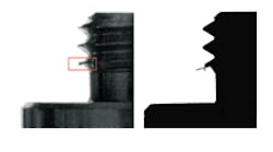
The resulting silhouette of the thread under inspection that was so accurate the system software was able to detect 160-micron-wide burrs. The company could measure the thread pitch, angle, and width with much better accuracy. This accuracy, combined with the higher speed, let the company measure its smallest-thread products and detect defects that would have previously gone unnoticed, in much less time than was once possible.
A diffuse backlight instead of the telecentric illuminator would have forced a compromise in performance or speed. All in all, the telecentric illuminator gave superior results without replacing the camera or lens. The boost in production speed and product quality more than paid for the up front system upgrades.
