|
Authored by: Joseph Torzillo & Edited by Robert Repas Key points: Resources: OSHA: Industrial Robots and Robot System Safety, www.osha.gov/dts/osta/otm/otm_iv/otm_iv_4.html Article: “Safety Rides the Bus,” |
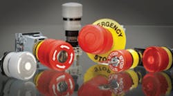
Emergency-stop switches, generally referred to as E-Stops, help ensure the safety of people and machinery by delivering a consistent and predictable fail-safe response. A wide range of electrical machinery need these specialized switches to meet workplace safety and established international and domestic regulatory requirements. E-Stops differ from simple stop switches that merely turn equipment off in that they offer foolproof equipment shutdown. This takes place through switch designs that need a twist, pull, or key to release the electrical contacts so the machinery can restart.
This file type includes high resolution graphics and schematics when applicable.
Fail-safe operation gives the E-Stop command priority over any sustaining function that keeps equipment running. Innovative switch designs prevent blocking, a wanton or accidental obstruction of the actuator with foreign objects, and teasing, a momentary actuation without latching the power circuit open, that may give premature or unreliable operation. Problems arise when contact blocks and actuators are improperly installed or if they separate because of vibration or other malfunctions. These realities have forced switch companies to improve switch reliability and, thus, safety.
Virtually all industry segments mandate E-Stops for safe operation. Unfortunately each area also has its own compliance requirements that designers must know. In addition, international standards may differ from local standards and compliance needs.
Simply stated, E-Stops should go on all machinery except for that in which an emergency-stop function would not lessen the risk. An E-Stop is only one part of a comprehensive safety system. Equipment designers must also consider safety functions, such as reversal or limitation of motion, deflection, shielding, braking, and disconnecting.
Safe emergency stopping
International standards state that emergency-stop functions must trigger on a single human action using a manually actuated control device. The stop must remain operational at all times and be designed in such a way as to stop the machine without creating additional hazards.
Resetting an E-stopped electrical system means first releasing the E-Stop that was originally activated. If more than one E-Stop activated, all must be released before the machinery can restart. Note that just resetting E-Stops does not restart the machinery; this action only permits restarting through normal procedures appropriate for the machinery involved.
Ergonomic, electrical, mechanical, and color requirements for E-Stops are quite specific. Many E-Stop controls use a distinctive mushroom-head pushbutton switch although wires, ropes, bars, handles, or foot pedals are sometimes employed. The E-Stop must also use direct mechanical action with mechanical latching such that when activated or pushed, it permanently opens the electrical contacts. To close the electrical contacts and let the machinery restart, the E-Stop actuator is manually unlatched with a twist or key release. Some E-Stop actuators can simply be pulled to close the electrical contacts. However, the pull approach may be less desirable from a safety standpoint than a twist or key release that needs more deliberate action by an operator.
Picking the right E-Stop
One of the first steps in E-Stop selection is in determining where the E-Stop fits within the machine control system and whether the particular application needs a Category 0 or Category 1-type emergency shutdown. The intended application often determines the placement, size, electrical specifications, mechanical qualities, ergonomics, color/legends, and the number of E-Stops. The key to picking the right E-Stop is a thorough understanding of the machinery and associated control system.
A second and equally important step is to determine what international standards, performance ratings, and codes apply. Requirements vary by industry segment, so standards for E-Stops on transportation vehicles differ significantly from those on process machinery or medical equipment and will be governed by different regulatory bodies. Regulatory bodies may also specify size, color, legend, contact terminals, and so forth.
It is often useful to construct or consult an existing E-Stop Series selector chart that vendors often supply. For example, EAO Switch Corp., Milford, Conn., provides a chart that allows easy comparison of key design factors for its multiple E-Stop Series. The chart simplifies selection of panel cut-out size, type of actuator, type and number of contact blocks, connectors, colors, and maximum electrical rating to come up with one or more appropriate models.
Like many vendors, EAO provides special enclosures, switch guards, palm guards, custom labeling, and other accessories to complete virtually any E-Stop application. Some accessories may be dictated by industry standards — such as the SEMI standards for semiconductor-fabrication equipment that mandate the use of palm guards. EAO and other vendors also offer services to assist customers in the design, engineering, and production to integrate E-Stops into HMI systems.
Standards and regulations for E-Stop implementation vary significantly by industry. Designers must have a good knowledge of the governing bodies and standards that apply. A few examples illustrate the diversity of requirements.
Cabinet X-ray systems used for diagnostic and therapeutic medical applications, industrial nondestructive inspection and thickness gauging, security inspection of baggage, and other imaging are closely regulated for operational safety. E-Stops are covered by standards and regulations of the FDA Dept. of Health and Human Services. CFR Title 21, Part 1020 — Performance Standards for Ionizing Radiation Emitting Products, Section 40, requires accessible emergency-stop switches and keyed lock-out switches to disable the system.
Semiconductor chips used in electrical and electronic devices are fabricated through a sequence of photographic and chemical-processing steps. The process includes lithography, steppers, etching, and deposition equipment. The complex process is governed by specific operational and safety guidelines set down by SEMI, a trade organization of semiconductor equipment and materials suppliers. SEMI S2-93 makes a clear distinction between emergency-off (EMO) switches and E-Stops, requiring the latter be clearly distinguishable from EMOs through the use of color (red), actuator shape (extended not mushroom), and labeling (“Emergency Stop”). It also specifies that E-Stops should stop all hazardous mechanical motion at the equipment interface, but not shut off associated equipment.
Large lifting and moving devices like gantry cranes may have a gantry-mounted cab which includes an E-Stop on the operator console. Smaller overhead cranes usually have a wired or wireless pendant control operated from ground level that includes an E-Stop. The chief regulating body for these massive devices is the Occupational Safety and Health Administration. OSHA 29 CFR 1910.179(a)(59) defines “emergency-stop switch” as a manually or automatically operated electric switch to cut off electric power independent of the regular operating controls. Another section, 29 CFR 1910.179(a)(61) defines “main switch” as a device controlling the entire power supply to the crane.
Future technology
The pace of change in E-Stop technology is steady, not revolutionary. By their nature, these devices must be recognizable, reliable, and rugged. Established standards, function, and familiarity dictate a certain beneficial inertia in new E-Stop developments.
Many advances are driven by norm changes for E-Stops, such as DIN EN ISO 13850:2008 that now requires mechanical latching and manual resetting of E-Stops. Most research and development is aimed at improving the safety and reliability of the switches themselves to expand their roles as lockout devices in worker-safety applications.
One area of current interest is making sure that the E-Stop itself will “fail-safe” should the actuator and contact block separate. The contact block has normally closed contacts that let power flow to the machinery. Pushing an E-Stop separates the spring-loaded contacts, and mechanical latching keeps them open, stopping the machinery. But what happens if the actuator separates from the contact block or the latching mechanism fails?
Separation of the contact block from the actuator renders an E-Stop ineffective. Current solutions include monoblock or unibody switches with a one-piece actuator/contact block, as well as switches with fail-safe-contact blocks that automatically shutdown the machinery if the actuator and contact block separate.
Other advances are application driven. For example, EAO’s Series 84 E-Stops were developed for handheld enclosures with slim back-of-panel depth as with teach pendants for robots. These versatile E-Stops also go in pendant controls for lifting and moving machinery. Application requirements have created a wide variety of available optional features and accessories for most E-Stop products such as illumination, protective rings, enclosures, guards, and legend plates.
E-Stops will continue to evolve to meet new standards and new applications.
|
Finding the right E-Stop E-Stops have evolved over the years with a general trend from larger 30.5-mm-diameter mounting hole sizes to smaller 22.5 and 16-mm sizes. The development of shorter, behind-panel-depth designs give designers convenient choices. Although each size and configuration offers special combinations of electrical and mechanical specifications, there are important design and safety features shared by most E-Stops such as teaseproof design, a twist-to-release actuator, and foolproof designs in compliance with international safety standards and codes. Many are sealed to IP65 oil and watertight standards, conform to color and legend standards, and often have available enclosures and legend plates. Robust, heavy-duty construction is the hallmark of the original 30.5-mm switches. Many, like the EAO Series O4 E-Stops, have stackable contact blocks, optional mushroom and key release actuators, and mounting options for 30.5 and 22.5-mm panel openings. Typically rated at up to 10 A, 600 Vac, these switches have silver contacts with available gold over silver or silver over palladium contacts along with silver-plated screw terminals or quick-connect terminals. Modern applications often demand a slimmed down E-Stop with 16-mm mounting. Innovative products have actuator shapes that prevents blockage from foreign objects, a black indicator ring visible from long distances, and availability of key release actuators. The 16-mm Series are typically rated at 5 A, 250 Vac, with a choice of silver or gold contacts, screw or solder quick-connect terminals, and optional ribbon cable terminals. Newer electronic applications need E-Stops with shorter behind-panel-depth. EAO’s Series 84 E-Stop, for example, features a short behind-panel depth of 18-mm maximum, a single monoblock construction, 22.5-mm mounting, and optional LED illumination that is visible from the side as well as front of the actuator. This Series is rated at 3 A, 120 Vac and 1.5 A, 240 Vac, has gold contacts, quick-connect/solder printed-circuit-board terminals, and ribbon-cable terminals. |
|
Applicable standards for E-Stops DIN EN ISO 13850: 2008 (Safety of machinery EN 60204-1: 2005 (Safety of machinery DIN EN ISO 13849-1: 2008 (Safety of machinery The following international standards for low-voltage switchgear and control gear must also be observed: EN IEC 60947-1: 2004 (Part 1: General rules), EN IEC 60947-5-1: 2003 (Part 5-1: Control-circuit devices and switching elements — Electromechanical control-circuit devices) and EN IEC 60947-5-5 Edition 1:1997 consolidated with amendment 1:2005 (Part 5-5: Control-circuit devices and switching elements — electrical E-Stop devices with mechanical latching function.) New EU requirements for U.S. exporters of machines became effective on December 29, 2009 when Machine Safety Directive 2006/42/EC (adopted in June 2006) replaced previous Directive 98/37/EC. The new directive acts as an umbrella for harmonized safety standards and adds a detailed list of 17 safety components in a new Annex V, including E-Stops. The new directive is designed to make design standards compatible with modern and future advances in technology. U.S. Standards for E-Stops fall under a number of different agencies: American National Standards Institute (ANSI) — B11, Electrical and Mechanical Equipment Guidelines ANSI/NFPA (National Fire Protection Association) — 79, Electrical Standards for Industrial Machinery Underwriters Laboratories Inc. (UL) — Category NISD, Emergency-Stop Device Food and Drug Administration, Department of Health and Human Services, Subchapter J — Radiological Health: CRF Title 21, Part 1020, Performance Standards for Ionizing Radiation-Emitting Products Semiconductor Equipment and Materials International (SEMI) — S2-93, Safety Guidelines for Semiconductor Manufacturing Equipment; S8-95, Safety Guidelines for Ergonomics/Human Factors Engineering of Semiconductor Manufacturing Equipment Most quality E-Stop switches, including those made by EAO, meet other compliance and rating bodies such as RoHS and Reach (Registration, evaluation, and authorization of chemicals), cUL (Canadian UL), TÜV (Technischer Überwachungsverein, a German safety-monitoring agency), SEV (a Swiss designation), and CE (European-Union) approvals. Depending on design and application requirements, many E-Stops are listed as UL category NISD emergency-stop devices. This rating covers two categories of E-Stop function as defined by the American National Standards Institute and the National Fire Protection Association in ANSI/NFPA 79, Electrical Standards for Industrial Machinery: Stop Category 0 — Immediate removal of power to the machine or mechanical disconnection (declutching) of hazardous elements. Stop Category 1 — Controlled stop with power available to stop the machine followed by removal of power once stop is achieved. The emergency-stop actuator provided in these devices must be a self-latching type. E-Stops with this rating have been investigated for their fire and electric shock safety in addition to their emergency-stop function. |
About the Author
Voice Your Opinion!
To join the conversation, and become an exclusive member of Machine Design, create an account today!

Leaders relevant to this article: