The Difference Between Machined and 3D Printed Metal Injection Molds
This file type includes high-resolution graphics and schematics when applicable.
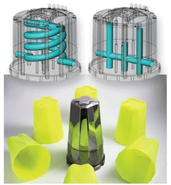
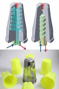
Direct metal laser sintering (DMLS) is a key technology used to print tool cores (also called mold inserts) for injection-molding processes. DMLS works just as it sounds — a 3D printer grows a part by sintering metal powder layer upon layer with a laser. This process lets engineers optimize the design of cooling channels. Cooling channels can be printed to any shape and closer to the part than subtractive methods can accomplish. The resulting conformal cooling channels save time, cut waste, and improve quality during the production of injected-molded parts.
The quicker an injection-molded part cools, the less expensive it is. One tooling manufacturer saw this relationship and invested in DMLS machines in 2003 to print optimized tool cores. Now, it runs production on eight EOS DMLS machines that work 24/7.
Linear Molds, Livonia, Mich., says 20 to 30% of its tooling sales are now 3D-printed inserts. The majority are injection-molding inserts. Lou Young, the company’s director of new business development, tooling & manufacturing, says, “Depending on the geometry, a (printed) tool will be more expensive, but the cycle time of the part will decrease.”
EOS application engineer Siegfried Mayer further explains why printed metal tool cores top machined tools. He says subtractive methods have several limitations when it comes to optimizing channel cooling. Only straight-line channels can be drilled, a limitation that can widen the distance between the cavity and the cooling channel. The result is an uneven dissipation of heat in the tooling material and uneven temperature levels on the cavity surface. This condition can also create uneven cool-down that cause internal stresses. These stresses can lead to warpage (which leads to higher scrap rate).
One perk of conventional tooling made by subtractive methods is that the tools can be made to virtually any size and cost less. DMLS prints are currently limited to about 9 x 9 x 9.5 in. in the current DMLS system, the EOSINT M 280. Young says a printed metal tool core can take upwards of 100 hr. to make and can cost about $10,000. A conventionally machined tool of the same size might only cost $4,000.
That price difference might come as sticker shock, considering the tool core may need a larger tool to support it, which can add even more cost. But the freedom of design available when devising cooling channels in these printed tool cores has proven to significantly cut part costs. And, conventional tooling tricks like using special copper heat conductors or other complex measures become virtually obsolete.
Mayer points to examples of cost savings that include work for Pôle Européen de la Plasturg, Oyonnax Cedex. The company saw a 20°C drop in tooling temperature leading to 20 sec saved on cycle time. Laser Bearbeitungs Center GmbH in Germany cut cycle times by 60% and reduced scrap rate from 50% to zero by optimizing tooling temperature.
Young reports that other types of manufacturing processes benefit from printed cooling channels. The limitation in most cases for vacuum-molding tools is size and low quantity. Even so, Linear Molds has made inserts for hot-stamping dies and for die-casting companies. Meanwhile, EOS reported a blow-molding manufacturer has benefited from conformal cooling design printed with DMLS. The printed PE bottle tool created a savings in cycle time of 4 sec.
Print materials
Materials account for a significant part of 3D-printed metal tool costs. While not as expensive as the time on the printer, the materials are more expensive than stainless steel. Metal tools printed on EOS machines are generally made of EOS’s MaragingSteel MS1. Young reports the material can make production tools just like P20 steel.
EOS spec sheets say MS1 can be machined after printing and can be post-hardened to more than 50 HRC by age-hardening at 490°C (914°F) for 6 hr. In both as-built and age-hardened states, the parts can be machined, spark-eroded, welded, micro shot-peened, polished, or coated.
Due to the layer building of DMLS, printed metal parts have a certain anisotropy that can be reduced or removed by heat treatment. Young says the material is 99.9% dense, making the porosity microscopic. And, a B2 surface finish can be had after polishing the tool. This surface is generally good enough unless the part needs an A2 surface for something as critical as a lens.
The tool life of a metal-printed insert resembles that of a machined tool. After post-hardening, 3D-printed metal tools can produce a million injection-molded plastic parts and thousands of die-cast metal parts. The evened-out temperature level that comes from an optimized printed tool can also improve tool life. This is true in die-casting tools because they see extreme temperature variations in use.
Printed metal inserts may need minimal postprocessing, besides hardening, on a case-by-case basis. And Young says his team sometimes post-machines production tools. They will add stock on the tools and then machine them to ensure geometric tolerances match.
How to design conformal cooling channels
Mayer mentions that the ultimate objective in tool-insert design is the creation of a mold temperature control system, which enables a constant and adapted temperature level for the material during the injection-molding process on each point of the molding surface. There are two design goals when creating a mold temperature-control system. One is to improve process speed, which usually involves lowering temperature to quickly cool parts. The other is to reduce scrap rate, which can be met with a higher temperature to get better surface quality. The better the surface quality, the less warpage and the fewer parts scrapped.
A few tips help meet these goals. Mayer explains that cooling-channel cross sections can be designed to almost any shape. Turbulence of the coolant (the desired high Reynolds number) within the system can be controlled by modeling different cross sections. Doing so will create turbulence close to the cavity along the entire path of the channel. A bended path in the design should improve this effect.
Changing the cross section or forking the cooling channel is a trick to help balance the two goals. Forking allows for additional heating and cooling in areas that cannot be reached by conventional methods. This feature actively influences cooling processes inside the melt. Evenly cooling the plastic melt minimizes warping, sink marks, and internal stresses. Mayer adds that the avoidance of internal stresses produces quality parts with the same amount of material, thereby reducing or eliminating scrap rates.
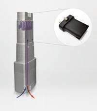
DMLS can also create combined systems with separated cooling and heating channels. There can be a split between main systems (for the control of the global temperature) and specific systems (for the handling of close-to-cavity critical temperatures).
Channel layout
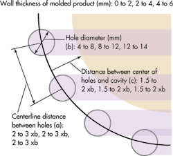
The channel diameter should be chosen based on the distance between the heating/cooling channel and the cavity. Mayer explains that if the channel diameter is correct and the design for the molded part is correct, the product can recrystallize uniformly and efficiently in the mold after the injection phase. But beware: Insert-printing veterans advise not to design the channel too thin.
According to Mayer’s experience, the optimal diameter should be between 4 to 12 mm (depending on the design of the product). Sometimes tool inserts are too slim to follow this rule (for example, a closely placed pair of ejector pins, thin walls, etc.).
In the case of complex geometrical limitations, much smaller diameters need to be designed. For example, when eliminating a hot spot, DMLS can build channels down to 1 mm diameter. However, specially treated fluids may be necessary to avoid clogging. Simulation software helps to find the right layout in such critical cases. FEA or flow-analysis software like Autodesk’s MoldFlow can help optimize the design.
About the Author
Lindsey Frick
Associate Editor
Lindsey has been an Associate Editor for Machine Design since 2012. She holds a Bachelor of Science in mechanical engineering from Cleveland State University. Prior to joining Penton, she worked in product design, packaging, development and strategy, and manufacturing. She covers the materials market and other areas of interest for design engineers such as 3D printing and methods to operate efficiently.


