|
Authored by: Al Neumann Edited by Leland Teschler Key points: • Revisions emphasize use of basic dimensions and geometric tolerancing as the preferred way of controlling the form, orientation, and location of features. Resources: |
The new ASME Y14.5-2009 standard on dimensioning and tolerancing reflects a culmination of effort extending over 15 years. It is a revision of the ASME Y14.5M-1994 standard. The M in the title of the old standard recognized the fact that it was metric compatible and was deemed no longer necessary, so it was dropped. There are many changes, improvements, and enhancements in this new standard from the earlier 1994 standard.
This file type includes high resolution graphics and schematics when applicable.
That said, it is impossible to address the implications of all the changes in a short article. But prospective users can benefit from general guide to some of the new changes. The new ASME Y14.5-2009 standard is progressing forward and reflects the state of the art in industry today. In general, the major change to the standard is that users will find it much easier to use and understand, but the fundamental geometric concepts have not changed.
Readers should also note that what follows are the views of someone who has been a member on the ASME Y14.5 subcommittee for the past 25 years. But they are opinions. They should not be interpreted as coming from the committee.
The sections in the standard have been reorganized to present the foundational principles first and then to build on these foundations. The reorganization has made the geometric concepts much easier to read and understand. The expansions, revisions, clarifications, and term definitions are woven through the fabric of the document. Below, we’ll outline a few of the major concepts.
The standard is progressing in its use of geometric tolerancing. It has been revised to emphasize and encourage of use of basic dimensions and geometric tolerancing as the preferred method of controlling the form, orientation, and location of features.
The use of direct-tolerancing methods, limit dimensioning, and plus-minus tolerancing are used to control the size of features only. The limits of size, Rule #1, has been expanded to include irregular features of size. Irregular features of size are features other than a sphere, cylinder, or two parallel planes.
In the new standard, a hex, square, cone, or other similar type of features can used as a feature of size and even as a datum feature as long as they are properly related with profile or other geometric controls. This small change was really needed and opens the door to many possibilities, especially in plastics and sheet-metal parts. Caution is in order, however, to make sure inspection procedures and CMM software can handle these types of features.
There are many major enhancements and clarifications in the datum section. The term True Geometric Counterpart has been replaced with the term Datum Feature Simulator. It is a little confusing at first, but there are two types of datum feature simulators, theoretical and physical. The theoretical-datum feature simulator represents the perfect geometry as a circumscribing cylinder for a shaft. The physical-datum feature simulator represents the collet or chuck that would be used on the shop floor.
The standard, being a product-definition standard, recognizes the fact that there are physical simulators but speaks in terms of the theoretical-datum feature simulator.
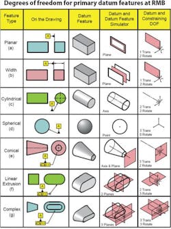
The degrees-of-freedom concept has been introduced recognizing that a part has six degrees of freedom, three translations, and three rotations. These degrees of freedom must be constrained to mathematically apply or measure geometric tolerances. The degrees of freedom approach in establishing a datum-reference frame is not new, it was first introduced in the ASME Y14.5.1-1994 standard and is now a staple of the new ASME Y14.5-2009 standard.
A degrees-of-freedom table has been added to the datum section. This table identifies primary datum features regardless of material boundary. The table describes the theoretical succession of events beginning with the identification of a datum feature on a drawing, its related datum feature simulator, the datum it establishes, and the degrees of freedom it constrains. This enhancement allows any feature to become a datum feature.
As a result of allowing any feature to become a datum feature, datum-feature modifiers have been expanded using new datum-feature modifier terms such as Maximum Material Boundary (MMB), Least Material Boundary (LMB), and Regardless of Material Boundary (RMB). These new terms replace the datum feature modifiers Maximum Material Condition (MMC), Least Material Condition (LMC), and Regardless of Feature Size (RFS).
The terms MMC, LMC and RFS were always confusing in the past when applied to datum features. Because even though they were referenced at MMC or LMC, they really applied at virtual condition. The term virtual condition is still used in the new standard but only for features and not datum features. The new datum-modifier terms MMB, LMB, and RMB provide a much-clearer definition of the boundary established by related datum features. It is also necessary now that irregular features of size can be recognized as datum features. There are examples in the standard explaining how to calculate these boundaries.
The datum section has implemented a new set of datum-feature simulator requirements. These datum-feature simulator requirements define the rules of engagement that datum-feature simulators play in establishing a datum-reference frame. There was some confusion in the past whether the datum simulators were fixed or movable. The simulator requirements basically state that all simulators are fixed at their basic location. However, in some cases it is necessary for a datum simulator to move or translate.
A new datum-feature translation modifier was added. If this symbol follows a datum feature referenced in a feature-control frame, it allows the simulator to translate from its basic location. The datum-feature requirements along with the translation modifier clarifies the process of establishing datums and datum-reference frames from datum features. It also clarifies the establishment of a secondary or tertiary datum relative to a higher precedence datum axis.
The new standard also added a movable datum target. It was brought over from the Y14.8 casting standard. It resembles the concept of the translation modifier, where the simulator translates to make contact with the datum feature.
The standard also adds a customized datum reference frame where expert users can reference datum features and specifically declare the degrees of freedom each datum feature will constrain. Customized datum reference frames are not a common application. Nevertheless, they are important when designers must override the stated datum-feature requirements.
The profile section also has significant enhancements. Profile tolerancing has been given its own section, reflecting the importance of this geometric characteristic. A nonuniform profile zone was added where the user can specify the applicable tolerance zone with dimensions shown on the drawing. This lets the design engineer specify any profile shape zone necessary within which the feature must lie.
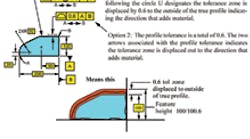
A new symbol, circle U, was added to profile tolerance. In the past, a design engineer wanting to specify an unequal profile tolerance on the drawing would draw a chain line in the applicable area. Two arrows were shown to displace the tolerance zone. In the new standard, the circle U symbol follows the toleranced value in the profile feature-control frame. This announces that an unequal tolerance is in effect.
The number following the circle U designates how much tolerance is displaced to the outside of the basic profile that adds material. This new symbol was first introduced in the ASME Y14.41 standard and is now in effect in the ASME Y14.5-2009 standard. The standard still allows, as an option, the chain line to define an unequal tolerance, but the circle U symbol is certainly preferred.
Since the release of the former ASME Y14.5M standard there have been major advances in technology in CAD, CMM, and CNC-type equipment. The new standard also takes advantage of these changes. It is a continuous improvement process. There is a trend towards applying geometric tolerancing to the solid model. The ASME Y14.41 illustrates how to apply the geometric-tolerancing symbology but the ASME Y14.5-2009 still defines the basic principles of tolerancing.
The ASME Y14.5.1-1994 Mathematical Definitions of Dimensioning and Tolerancing standard is still valid and provides a solid mathematical foundation with an update coming for the new Y14.5 standard. There is also an update planned for the ASME Y14.5.2 Certification of Geometric Tolerancing Professionals to the new ASME Y14.5-2009 standard. The Y14.43 Dimensioning and Tolerancing Principles for Gages and Fixtures also has a planned update to the new standard. Currently a new standard Y14.45 Measurement Data Reporting is in the works to standardize the reporting of measurement data on geometric toleranced parts.
For additional information on the subject, Al and Scott Neumann have just completed the book, Geo Tol Pro. They also have a Blu-ray Disc set and provide on-site training programs to the Y14.5 standard.


