This article was updated May 30, 2023. It was originally published Sept. 8, 2011.
3D solid modeling can be a double-edged sword for engineers. It lets them express their creativity and easily design wildly complex components and assemblies. But that design freedom can lead to designs impossible or impractical to manufacture in the machine shop. When that happens, it often leads to costly redesigns, and the cause can usually be traced to the engineer’s lack of exposure to machine-shop settings and process.
Here are some tips on how to avoid a few of the problems machinists face when following problematic designs and how to make designs more economical to manufacture.
Tip #1: Use stock sizes. An engineering team might find the material it wants in the size it needs on a vendor’s website or catalog, only to find it is unavailable when the team tries to order it. This is not much of a problem if designs are based on using standard-sized materials in the coarser fractional dimensions such as 1/8, 1/4, 1/2, 5/8 and 3/4 in.
Avoid the 1/16-, 7/16- and 9/16-in. sizes because most mills either don’t stock them or require a special run. (This applies more to bar and plate than to sheet stock and round bar.) Should designs call for metric dimensions, as many medical products do, consider that stock metric material is sometimes more difficult to obtain in the U.S.
Tip #2: Consider workholding. Design parts so that they have at least two opposing parallel flat surfaces or a truly cylindrical surface. This lets them be easily gripped by conventional vises and tooling, which speeds production. Parts without these features could require custom fixtures to hold them while being worked on. This can boost manufacturing costs significantly.
Tip #3: Tool length-to-diameter ratio is all-important. Machine shops often get drawings that require deep pockets with small radii on internal corners or, worse yet, no radius at all. Milling is done with round tools (end mills) and typically work on a plane perpendicular to the feature face.
As a rule, the deeper the pocket, the larger the cutter diameter needed. Smaller radii can be produced—and even square internal corners—but they require longer machining times, or alternate forms of machining such as broaching or electric discharge machining (EDM), which are both time-consuming and expensive.
Keep in mind that a standard off-the-shelf end mill has a length-to-diameter ratio of 2 to 1. Although many cutters exceed this ratio, there are good reasons for maintaining this standard. Small internal corner radii necessitate using small cutters, which means a higher risk of tools breaking, longer machining time and higher costs.
Tip #4: Drafts, angles, and undercuts are critical. There are many standard angle cutters on the market, but it’s important to consider draft angles. Whenever possible, try to design around those standard cutters that are readily available cutters. There are several great online and hard-copy catalogs available for referencing available tooling.
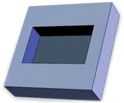
If there’s a pressing need to add an angle on a feature such as a square or rectangular pocket, remember that the radius in each corner increases the higher it goes up the sides when using angle cutters. If your design requires constant corner radii, it will require expensive 3D machining.
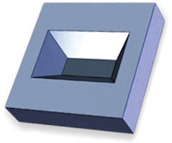
Tip #5: Avoid undercuts. Undercuts are created when any angles create a pocket or slot with an opening larger at the bottom than at the top. Sometimes this is referred to as a “reverse draft.” Reverse tapers or drafts on blind pockets cost more to make than straight wall or conventional drafts. For rectangular machined pockets, consider the requirement for radii in each internal corner.
When a pocket requires bottom contours, engineers must take into account that the pocket will require 3D machining and ball-end mills to create that contour. Engineers must allow for radii in all inside corners as well as at the intersections of the bottom and side walls.
Tip #6: Drilling holes. Don’t forget how dimensions of basic features like drilled holes affect cost. Deep holes with small diameters, extreme straightness requirements, and off-center intersections with other holes or features tend to be more costly. It is hard to say just when a hole becomes too deep for its diameter to make regular drilling impractical. Much depends on the nature of the material being drilled and other factors.
Tip #7: How will edges be treated? Will they require a fillet or chamfer, or just be left sharp? While designing, it is easy for engineers to get carried away with component details. Machinists often see small chamfers added on parts where the designer is trying to show a requirement for edge breaks, sometimes referred to as eased edges.
Simply put, this means “no sharp edges” and in machine shops, this is understood. In these cases, it is best for designers to omit the feature and instead add a note on the drawing detailing the need for eased edges.
Most machine shops use CAM software to create parts directly from solid models. Sometimes, programmers find it difficult to select the correct faces or edges when “small” chamfers or fillet features are included on models. Larger fillets and chamfers do not present a problem. In general designers should think before adding any feature. Then add them if they are absolutely necessary.
In short, designers should keep these considerations in mind:
- Can the model’s feature be machined using conventional methods and tooling?
- Can existing tools make this part or feature, or will it need custom tooling?
- Are there features on this part that make it easy to hold securely during machining, or will special fixtures be needed?
- Are there unnecessary fillets, chamfers or draft angles that can be eliminated to make the part less expensive?
- Are there internal reverse angles or drafts in blind pockets that need to be eliminated?
- Does the design avoid sharp inside corners wherever possible?
Whenever there’s a question regarding a design’s feasibility from a machinist’s standpoint, call on a local machine shop. Most will be happy to make suggestions and give advice on practical machining matters. Often, just a few simple tweaks to a design can slash costs.
RELATED
CNC Guide (Part 2): How Changing Features Can Mitigate Manufacturability
Top Tips on Designing Parts for CNC Machining
Why Moving to Solids Makes Sense
Best Practices for FDM 3D Printing
Milton Florest was president of Tooling Research Inc. when this article was originally published.
