Authored by: |
Most people think of parallel-drive systems as those found in Cartesian/gantry robots. But parallel-drive systems can also be viewed as two or more linear motors working in parallel from a single drive controller. This covers the Cartesian/gantry-style robots plus other major areas of motion control, such as high-precision and ultrahigh-precision single-axis robots having resolution and position accuracy in the subnanometer to high-picometer range. These systems go into such areas as optics and microscopes, semiconductor manufacturing, machine tools, actuators with high force, material-testing equipment, pick-and-place work, assembly operations, handling machine tools, and arc welding. All in all, there are applications in both the micron and submicron world.
Parallel-drive issues
The major issue with all parallel-drive systems is orthogonal alignment: the ability to keep the parallel axis square. In such mechanically driven systems as screw, rack and pinion, belt, and chain, the main issue is the binding of the mechanical system from misalignment or stacked tolerances. In direct-drive systems, there is an added issue of sine error introduced because of installation errors and variances in the linear motors.
The most common practice to overcome these issues is to drive and control each side of the parallel system independently, but sync them electronically. The cost of such a system is high because it needs twice the drive and position-sensing electronics of a single-axis system. It also adds synchronization and tracking errors that can degrade the performance of the system.
The thing that makes it possible to connect linear-shaft motors in parallel is a highly responsive motor. The dynamic motion generated by any two identical linear-shaft motors is the same when given the same control signal.
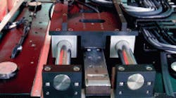
As with all parallel-drive systems, the linear-shaft motors must physically couple with a mechanism that lets the axis have only a single-degree-of-freedom movement. This makes parallel linear-shaft motors act as a single unit to permit operation with a single encoder and single servodriver. And, as a properly installed linear-shaft motor operates without contact, it cannot introduce any mechanical binding into the system.
These statements are true for any noncontact linear motor. Linear-shaft motors differ from other noncontact linear motors in several areas that let them work well in a parallel application.
The design of the linear-shaft motor places the permanent magnet in the center of the electromagnetic field, making the air gap noncritical. The coil completely surrounds the magnet, so the net effect of the magnetic field is force. This virtually eliminates any force variation caused by a difference in the air gap, either through misalignment or machining differences, making alignment and installation of the motor simple.
However, sine error — a major issue — could cause force differences in any noncontact linear motor.
Linear motors, like linear-shaft motors, are defined as synchronous motors. In effect, current is applied to the coil to form an electromagnet that synchronizes to the magnetic field of the permanent magnets in the magnet track. Force in a linear motor is generated from the relative strength of these magnetic fields and the angle of their intentional misalignment.
In a parallel-drive system, all coils and magnetic tracks become a single motor when all their magnetic fields are perfectly aligned. However, any misalignment of the coils or magnetic tracks will cause misalignment of the magnetic fields, producing different forces in each motor. This force difference can, in turn, bind the system. So sine error is the difference in forces produced by the misalignment of the coils or magnetic tracks.
Sine error can be calculated by the following equation:
Fdif = Fgen × sin(2πDdif/MPn-n)
where Fdif = force difference between the two coils, Fgen = force generated, Ddif = length of misalignment, and MPn-n = north-to-north magnetic pitch.
Most linear motors on the market are designed with a north-to-north magnetic pitch in the range of 25 to 60 mm under the guise of trying to reduce IR losses and the electrical time constant. For example, a misalignment of just 1 mm in a linear motor with a 30-mm n-n pitch will produce a power loss of approximately 21%.
The linear-shaft motor compensates for this loss by using a much longer north-to-north magnetic pitch that reduces the effect of sine error caused by accidental misalignment. The same misalignment of 1 mm in a linear-shaft motor with a 90-mm n-n pitch will produce only a 7% power loss.
Parallel-drive systems
Truly accurate positioning is only possible for high and ultrahigh-precision single-axis robots when the feedback is directly in the center of mass of the work point. The force generation from the motor should also focus right in the center of the mass of the work point as well. However, it’s typically impossible to have the motor and feedback in the exact same location!
Putting an encoder in the center of mass and using parallel linear-shaft motors equally spaced from the center of the mass gives the desired feedback and force generation in mass center. This is not possible for other types of parallel-drive systems that need two sets of encoders and servodrives to create this type of parallel drive.
The single drive/single encoder works best in ultrahigh-precision uses and gives gantry-system builders a huge advantage. In the past, systems may have had two different motors driving separate ball screws using two different controllers that were electronically connected, or even two linear motors with two encoders electronically connected with two drives. Now the same actions can come from two linear-shaft motors, one encoder, and one amplifier/driver, as long as the stiffness in the system is sufficiently high.
This is also is an advantage for applications needing extremely high amounts of force. It is possible to connect any number of linear-shaft motors in parallel, thus adding their forces together.
