Here’s a little quiz to test your knowledge of how worm gears operate:
• A self-locking gear cannot be driven by the load in the opposite direction from its intended direction of rotation. (True or false?)
• When worm gearing is self-locking or irreversible, this means that the worm gear cannot drive the worm. (True or false?)
• It is usually impractical to design irreversible worm gearing with any security. (True or false?)
This file type includes high resolution graphics and schematics when applicable.
The correct answer to all of these statements is true, under certain conditions. The first statement is from the article “Self-locking gears: what they are, what they do,” PTD, 5/89. The second and third statements are from Machinery’s Handbook, 24th Edition.
So how do you reconcile these seemingly contradictory statements: the load cannot backdrive in the opposite direction, yet it is impractical to design irreversible gearing? The explanation lies in understanding the difference between gear design theory and the practical aspects of applications engineering.
Applications teach hard lessons
Within the last 3 years, our failure analysis engineers investigated two accidents involving worm gears where the user was injured. In each case, a designer selected a worm gear speed reducer from a catalog and incorporated it into a lift device intended to raise and lower people. In both cases, the designer was under the impression that the load (person plus platform) could not self-lower. They both relied on self-locking worm gears to hold the cargo in a desired position and genuinely believed that no brake was necessary to supplement the worm gear in such a critical application.
Friction angle experiment
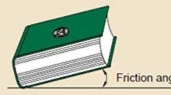
To understand the difference between conventional theory and application of worm gears, lets first conduct an experiment. Place a quarter on a book that is lying flat on a table. Slowly raise one end of the book until the quarter begins to slide downward. Then lower the end slightly so the quarter is stationary. The angle between book and table, which just prevents sliding, is called the static friction angle. Its value depends on the amount of friction between the quarter and the book.
Now with the book held at the friction angle, lightly tap the book and notice that the quarter slides down. The vibration (tapping) changes the friction from static to dynamic, which has a lower value, thus allowing the quarter to slide.
A threaded fastener works the same way. The helix angle of its threads is small enough to prevent it from turning under static load. But add vibration, and the fastener loosens. The helix angle and the friction coefficient are the key elements in determining the friction angle that makes “things stay put.”
Worm gear theory
A number of references will help you understand the theory of worm gear geometry. Some examples include Machine Design Fundamentals by Uffe Hindhede (which is well written and requires a minimum of mathematical skills), Machinery’s Handbook, and the 5/89 PTD article mentioned earlier.
All theoretical analyses of self-locking worm gears deal with static conditions. In such an analysis, the load on the worm gear can’t drive the worm if the coefficient of friction between worm gear and worm is larger than the tangent of the worm’s lead angle. In other words, the friction angle must be larger than the lead angle to prevent backdriving.
Consider a worm gear speed reducer with a lead angle of 5 deg and a static coefficient of friction of 0.13. The arctan of the coefficient of friction is 7.4 deg, and is the friction angle. Because the friction angle is larger than the lead angle, a worm gear with a 5-deg lead angle is considered statically self-locking. If, however, this self-locking reducer is subjected to shock and vibration, the friction coefficient between worm and gear may suddenly drop. If it drops to 0.08, then the friction angle (arctan of 0.08) drops to 4.6 deg, which is now less than the lead angle of 5 deg. During the time that the friction coefficient is 0.08, the gears are no longer self-locking and back-driving can occur. Once started, backdriving usually continues because the friction coefficient decreases with increasing speed.
Conversely, where shock and vibration are not present, the self-locking feature will probably perform as intended. However, such vibration-free applications are rare. Also, other factors, such as temperature, can affect friction.
Design guidelines
Generally, a system designer is responsible for selecting the correct components so the system performs in its intended manner. To do so, the designer should be aware of the conditions where self-locking may or may not occur. Here are some suggested rules for designing with worm gear speed reducers:
• If safety is a potential issue, always add an adequate braking device, whether or not vibration and shock are expected. Remember: “It is usually impractical to design irreversible worm gearing with any security. If irreversibility is desired, it is recommended that some form of brake be employed,” says Machinery’s Handbook, page 1933.
• If you want to use the self-locking feature of a worm gear speed reducer as a brake where there are no potential safety issues, use Machinery’s Handbook or similar design references. Contact the worm gear manufacturer to determine friction coefficients for your specific conditions and obtain advice on selecting a reducer.
Dr. Albert V. Karvelis is vice president, Packer Engineering Inc., Naperville, Ill., an engineering consulting firm.

