How to diagnose a noisy gearbox
Sometimes a gearbox problem can be easily identified by the sound it makes during operation. Conversely, other situations exist for which “normal sounding” and “abnormal sounding” are simply too ambiguous to be of any diagnostic value.
Basic review: The science of sound
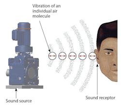
The study of sound is a complex science. Careers have been made and volumes written specifically regarding the science of sound. In short, sound is defined as the back-and-forth vibration of particles in a medium (such as air, water, or a solid) that are created when a traveling wave passes through the medium. By virtue of this back-and-forth motion, a pressure wave is created, which depends on the amount of air pressure fluctuation that the sound source creates. In other words, when something vibrates, it causes the particles near it to vibrate as well. These particles likewise bounce into and away from each other, forming high and low pressure waves that form the sound we hear when these waves reach our ears.
This file type includes high resolution graphics and schematics when applicable.
Three elements make up sound: a sound source, such as a gearbox; a medium — typically air; and a sound receptor — the human ear, for example. Note: In contrast with the scientifically defined term of sound, noise is simply defined as undesirable sound.
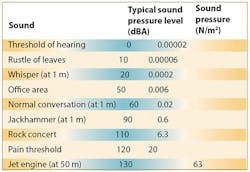
Sound pressure is usually expressed in units of Newtons per square meter (N/m2), also known as Pascal or simply Pa. The lowest sound pressure humans can hear is approximately 0.00002 Pa. At the other end of the scale, sound pressures of approximately 20 Pa are discomforting.
Given this broad spectrum in which sound pressure can be perceived by the human ear, it is more convenient to refer to sound pressure levels when addressing questions of sound.
Sound pressure level Lp can be defined with mathematical logarithms that compare a sound pressure against an established sound pressure standard:
where p = Sound pressure of the wave
p0 = Standard reference sound pressure — 0.00002 Pa = 20 µN/m2
The stated value for p0 is used because it is near the lower limit of human audibility. While mathematically dimensionless, the value is referred to as a decibel (dB), named after physicist Alexander Graham Bell.
Weighing scales referred to as the A, B, and C scales approximate what the human ear hears. Typically in industry, the A weighing filter is applied in sound pressure level equipment and discussion. This is because people hear high frequency sounds better than low frequency ones, and the applied A weighing factor deemphasizes the lower frequencies from a reading. When representing results gathered from sound measurements, it is common to include the scale setting that was used to measure the data: For example, dBA represents a sound pressure level measured with the A weighing factor applied.
Many companies offer specialized equipment designed to measure sound pressure levels; the size, function, and cost of this equipment varies widely. In an industrial environment, it is common to use handheld meters for such evaluations. Often called decibel (or simply dB) meters, they provide a simple, portable, and economical way of measuring sound pressure levels. Many are available with built-in filters that allow the measurement to be displayed on the A, B, or C weighing scales.
As with any sensitive piece of equipment, calibration is vital, so specialized sound calibrators should be used with the meters to ensure accuracy.
Understanding gear sounds
Gearboxes and gearmotors generate operational sounds in a variety of ways: Gear mesh, bearing rotation, lubricant splash, oil pump operation, and the interaction of the gearbox within the machine structure all contribute to the overall sound generated by a gearbox during operation.
Page 2 of 2
With regard to individual gear components, the tooth finish of the gearing itself contributes to the sound generated during operation. For example, helical gearing that has been hobbed only tends to be louder than a comparably sized helical gearset that has also gone through a post-hobbing tooth finishing operation. For this reason, shave or grind finishing is performed on gear teeth to minimize or eliminate the rough tooth surface finish that the hobbing operation often generates. Note: In terms of tooth finish, the gearset's rotation speed also plays a significant roll in the resulting sound. Very little difference, for example, would be noted between a hobbed-only gearset rotating at 30 rpm versus a ground-finished gearset of the same size also rotating at 30 rpm. Conversely, if the gearset's rotational speed increased, one would notice a marked increase in sound from the unfinished set compared to the finished one.
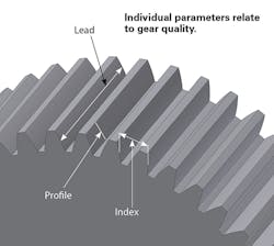
Various organizations such as the American Gear Manufacturers Association (AGMA) have established quality rating standards based on tolerances associated with each of these parameters. Given these factors and their influence on how gears in mesh interact with each other, it makes sense that a gearset manufactured to a lower quality rating would likely generate more sound than a comparably sized gear manufactured to a higher quality rating.
Design choices that minimize operational sound are not limited to the aspects discussed so far. Rather, several other important factors can serve to actively lessen sound. Incorporation of these sound-reducing options, however, may yield unfavorable consequences in other areas of the design. Ultimately it is up to the gear designer to understand and prioritize design intent.
Consider the gearbox as a whole: Certain noises may provide an indicator of an undesirable situation. As an example, nicks or dings on the gear teeth could easily yield a constant “clicking” sound as the face of the offending tooth (or teeth) comes into contact with the face of the mating gear. Typically, gearbox manufacturers “run test” a product after it has been assembled and prior to shipment. Performance data — including sound — are measured, evaluated, and compared against nominal values to ensure that the product is operating within established limits.
Quantifying gear noise
As noted earlier, noise is a subjective concept. To call a gearbox manufacturer and say that a gearbox is “noisy” may be a frustrating experience for the user if the noise claim can't be clearly described or quantified. Fortunately, there is a governing mathematical formula for sound pressure. This formula, combined with some applied mathematical operations, provides a way to more clearly define the sound that an installed gearbox is generating.
Subtracting ambient noise from a total measured value returns the sound pressure level from a particular source.
To begin, let LP,BACK and LP,SOURCE represent the sound pressure levels of the background and source respectively. Then:
and LP,TOTAL = Total measured sound pressure value.
With these sound pressure levels defined, it is mathematically proven that:
In essence, this equation provides the ability to calculate the sound from a source when the total sound LP,TOTAL and background sound LP,BACK are known through individual measurements.
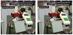
To estimate the sound generated by a gearbox, one must first measure the total sound in the area where the gearbox is located. Two notes of caution: First, the gearbox should be running while this measurement is taken; second, the meter typically should be held at a distance of 3 ft from the unit.
Once this measured value Lp,TOTAL is noted, turn the gearbox off and again measure the sound level in the same area where the first measurement Lp,TOTAL was obtained. This second measured value is Lp, BACK. To calculate the sound that the gearbox is generating in operation Lp, SOURCE, simply insert the measured values into the equation to obtain the result.
For example, say an engineer must determine the sound generated by a gearbox while running in an application. Assume that a handheld sound meter determines total measured sound is 77 dBA, and that this value is Lp,TOTAL as measured around the area of the gearbox while operating. Finally, let us assume that the sound pressure level in the same area as LP,TOTAL when the gearbox is off is LP,BACK and measured at 73 dBA:
Inserting these values into the equation:
Using a scientific calculator, LP,SOURCE = 74.8 dBA.
Depending on the application and setup, it may be possible to distinguish between motor sound and gearbox sound using the same mathematical procedure.
For new equipment installations, baseline sound measurements should be recorded for future reference. Then subsequent sound measurements can be compared to this baseline value for evaluation.
For your reference
These tips provided by Todd Bobak Chief R&D engineer Sumitomo Drive Technologies Chesapeake, Va.
American Gear Manufacturers Association - AGMA 914-B04 Gear Sound Manual, 2004; AGMA 6025-D98 Sound for Enclosed Helical, Herringbone and Spiral Bevel Gears,1998
Basaraba, Bruce; Archer, James, IPT's Rotating Equipment Handbook, IPT Publishing and Training Ltd., 1995
Halliday, David; Resnick, Robert, Fundamentals of Physics. John Wiley & Sons, 1988
