Precision motion evolution: Early history of precision motors (1960s to 1980s)
In this article, we cover the development of early step motors and early servomotors.
Co-author: Dan Jones, president of Incremotion Associates.
Today’s precision position motor family has two major adherents, the step motor and the brushless permanent magnet (PM) motor. Both types have continuously evolved over the past 40 years. These two prime movers have provided many industries the muscle power for driving precision positioning systems in office automation, factory automation, instrumentation, aerospace and many other markets. While the brush dc motor stubbornly holds into many applications, the brushless PM motor has gained ascendancy over it in an ever-widening range of applications.
The past 50 years have seen step motors and servomotors alternately gain the top position in the precision motion market only to lose it to the other. The shifting market fortunes of the brush/brushless servomotor versus the step motor have been driven by various technological breakthroughs, such as the rare earth magnet, the bipolar and field effect transistor (FET), the microprocessor, and the digital signal processor. Before 1955, the ac induction servosystem using a two-phase ac motor was the paramount system for positioning applications. The step motor began its initial growth spurt in the 1960s, overtaking the brush and brushless servomotor driven systems in the early 1980s. Since then, the brushless dc and ac-driven servos have significantly expanded their market share to recapture the market lead by the mid 1990s. Today, major step motor attributes have been combined in a closed-loop, brushless ac servodrive system.
The step motor has a number of different versions — it doesn’t suffer from an identity crisis. Whereas, the synchronous PM motor has been called the brushless dc motor, brushless ac motor, ac servomotor, brushless servomotor, and other names, according to how it was being electronically driven. The range of identifying names depicts the various historical and market roots for brushless PM motors. This motor uses a permanent magnet to generate the magnetic field from the rotor. A wound field creates the stator’s magnetic field. The interaction of these two fields creates torque and speed. The step and brushless PM motors use high-performance magnets, such as samarium cobalt or neodymium iron boron, to generate the highest possible torque from a given package size.
Both motor types require electronic drives composed of power and control electronics. These drive packages provide the necessary electronic signals to drive or move both motor families in prescribed motion profiles. Different strategies are used to control the step motor and brushless PM motor. The step motor possesses an internal magnetic positioning capability when driven in an open-loop (no feedback) control strategy. The servomotor requires various measured feedback signals (commutation, current, velocity, and position) for comparison with the input signals in a closed-loop control strategy. The history of electronic drives development closely parallels motor development.
Early step motors
The first step motor, a bidirectional variable reluctance type, was developed for the British Navy in 1933. It was used as a remote position repeater for a compass and gun pointer direction indicator. The drive was crude but effective for these slow constant speed applications. The system was later adopted by the U.S. Navy during World War II. The step motor was used in a limited number of primitive digital control systems through the 1950s. The predominance of closed-loop continuous ac induction servos from 1944 to 1957 was soon overcome by the PM step motor and the availability of digital measuring devices and control logic necessary for all-digital systems.
By 1960, the PM step motor (large-angle type) had become the primary step motor in use. There were no cures for resonance or shaft velocity vibration other than stop the step motor shaft and restart the motion. The key attributes were the PM step motor’s open loop position accuracy of +5% and the non-cumulation of position error. The brush servo (closed-loop) system or small instrument ac (two-phase) servomotor system required careful stabilization of the analog feedback signals (velocity and position). It was a daunting task to close a servo loop and properly stabilize the servo motor in 1960. Typical step motor applications in 1960 included drone control readouts, railway car sorting indicators, portable weighing station indicators, and digital differential altimeters.
The ac synchronous inductor motor
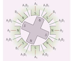
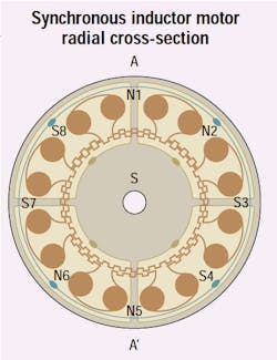
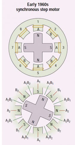
A few years previously, General Electric had developed an ac synchronous inductor motor for use in low-speed smooth motion applications. This motor was designed to operate with a 60-Hz, 115-Vac signal and generate smooth continuous motion equivalent to the movement of an analog clock’s second hand. In 1961, Snowden and Madsen of Superior Electric Co. announced a new rendition of the synchronous inductor motor which would become famous by another name, the hybrid step motor.
Within two years hybrid step motor sales eclipsed that of ac synchronous inductor motors. The hybrid step motor drive scheme in 1961 also used a bifilar winding driving the two-phase winding halves A1, A2, B1, B2. The power supply current was in a single direction or in a unipolar excitation scheme. Unipolar-based drive circuits remained popular throughout the 1960s and 1970s.
The Snowden-Madsen paper also displayed another basic drive scheme; A, A-, B, B-, which represents the bipolar drive scheme. Two power supplies are needed to support a bipolar (bidirectional current) drive scheme. While not popular in the 1960s and 1970s, the bipolar drive is the most popular drive scheme today. One of the first applications for the hybrid step motor came from the factory automation market. When this step motor was mechanically coupled to a five-pitch lead screw, the combination provided a step-by-step motion of 0.001 in. This step increment worked very well with tables on machine tools, laboratory, and business machines. Superior Electric was the pioneer of the hybrid step motor under the SLOSYN brand name to be joined by others by the late 1960s.
Variable reluctance step motors
The third major step motor class that gained popularity in the 1960s was the variable-reluctance (VR) step motor. VR step motors offered low cost, low rotor inertia, moderate speed and high running torque at the expense of non-linear torque versus current, high inductance sensitivity to load changes and high resonance potential. VR step motors were driven with unipolar currents in dedicated drives different from the drive techniques used with PM step motors. The popularity of VR step motors used in computer peripherals peaked in the mid 1970s and began a decline in market share by 1980. Many VR step motors drove the paper feeds in both electronic printers and business machines. Better drive techniques, higher torque capabilities, smaller step positions, more effective manufacturing and cost control let the hybrid step motor gain the higher performance segment of the step motor market.
Can stack step motor
The fourth major step motor type attacked the VR step motor’s market share from the low performance segment of the growing step motor market. The can stack or claw-tooth step motor uses a low cost construction consisting of a series of sheet metal parts punched and formed into cups with teeth (claws) that surround the bobbin coil assembly. The two stator assemblies (for two phases) are indexed to obtain alternate N-S-N excitation.
The drive strategies were the same as the hybrid step motor and the other (large angle) PM step motor. Unipolar drives with current flowing in a single direction into a two-phase bifilar winding were the most popular method of driving these lower cost two-phase step motors. Popular step angles congregated around 7.5 degrees-perstep to 15.0 degrees-per-step. These can stack two-phase PM step motors grew in popularity in the 1970s and moved into higher volume lower cost applications in computer printers, disk drives, and automotive actuators. The can stack step motor’s performance was sufficient to capture much of the lower performance computer peripheral market from the VR step motor by the end of 1979.
The microprocessor
The microprocessor burst into the motion market in the early 1970s. It provided a near perfect control “clock” needed to time the pulse trains to the step motor. Variable pulse rates, then reaching speeds of 1,000 to 2,000 pulses per second let the step motor accelerate and decelerate under close timing control.
Overcoming the step motors’ phase inductance and delayed phase current build up required special drive circuitry. Series resistance techniques, first reported in 1970, represented by L/nR, where n = 2 to 4, lower the step motor’s electrical time constant which allows fast phase current rise and fast accelerating torque development. Other drive techniques such as bi-level and dual voltage techniques were developed to overcome the delay in current caused by higher winding inductances.
The final problem with driving a step motor in an open-loop (no sensor feedback) mode is the inherent capability to experience velocity resonance or vibration which can lead to loss of synchronism and all motion. A number of techniques and circuits were developed to stabilize step motor shaft motion, under the category of damping techniques. These new circuits continued to gain sophistication in the 1960s and 1970s. By 1975, the digitally controlled step motor (in most forms) was growing at a faster rate than the analog servosystem driven by brush motors. A new motor type was emerging from use primarily in the defense and rotating media industries, the brushless dc motor or brushless PMDC motor.
Early servomotors
The first dc motor called “brushless” was developed by H.D. Brailsford in the mid 1950s. This pioneering effort greatly influenced later work. Once the mechanical brushes were eliminated, these dc motors could operate for surprisingly long periods with great reliability. The Brailsford motor used spring contacts to start or commutate the drive transistors. Once in motion, the contacts flew out, permitting true brushless operation. This pioneering effort greatly influenced later designs. The Brailsford motor was then used in applications involving remote equipment such as portable pollution monitors.
The U.S. Air Force was very interested in brushless dc motors because of the major problems with dc motor brushes at high altitudes of 20,000 ft and above. With the start of space exploration, brush problems became critical. Brush life in space was then limited to minutes. High peak torque and linear torque-speed current operation could only be obtained with a PMDC motor in 1960. When Goddard Space Center surveyed the American motor industry in 1962, only one U.S. manufacturer had a working bread board model of an electronically commutated brushless dc motor. Sperry-Farragut, located in Raleigh-Durham, N.C., developed the first of a series of brushless dc motors that would be used in various U.S. space program applications throughout the 1960s. These brushless dc motors were commutated by photoelectric sensing of rotor position and possessed efficiencies more than twice as high as comparable ac servomotors. The induction of silicon-controlled rectifiers (SCRs) in 1957 provided the solid state drives used to power these brushless dc motors.
Brushless dc motors in space and Industry
Brushless dc motors (and their associated SCR drives) were capable of 1 to 375 W in space qualified applications by 1965. The oxygencirculating system in the Apollo and the coolant pump in the Saturn I-B and Saturn V launch vehicles used brushless dc motors.
By 1965, both Westinghouse and GE were building brushless PMDC motors. In 1970, GE was building 200-W brushless traction drive motors for the Lunar Rover. Hall devices developed in 1967 were beginning to replace optical commutation as the preferred solid state switching solution. The Hall device developed a voltage pulse when moving through a magnetic field that can signal sequential switching of the stator windings. Philips Electronics in Holland marketed the miniature silicon chip version of the Hall IC in 1972.
In 1970 Siemens Electric Co. developed the first commercial product, a battery-powered tape recorder using a two-phase brushless dc motor and electronic drive for the then unheard of price of $25, which included the electronic drive as well. The same brushless dc motor and drive family was still in production 10 years later. Two drive methods for these motors depended on the step motor’s unipolar (star) and bipolar (bridge) drive circuits. The double H bridge method became the most popular drive scheme in the early 1980s. By 1974 most higher performance applications were using a three-phase drive scheme. This three-phase, full-wave scheme, the trapezoidal waveform drive, is still in use today.
A typical example of the full brushless PM servosystem from 1975 displays a brushless dc tachometer used in conjunction with an optical position encoder and a commutation encoder to provide velocity, position, and commutation feedback signals, respectively. The three separate sensors provided commutation, velocity, and position information to control the analog brushless dc servosystem in incremental (start-stop) motion.
The PM brushless motor has a different cross-section than a PM brush motor or an ac induction motor. The stator winding configurations in a PM brushless motor and a three-phase ac induction motor are equivalent. But, in the PM brushless motor, the permanent magnets are attached to a magnetic rotating hub. The rare earth PM brushless motor possesses superior acceleration characteristics compared to all other motor types. The year 1970 brought power efficiencies of 80%, which was far higher than any other precision motor technology (under 1 KW) at the time. Two major classes of inner rotor brushless PM motors emerged from the early designs. The first class, the surface magnet type, is often called the conventional brushless PM motor. The second class, the buried magnet type, would become a major player in the brushless servo markets in the late 1990s.
Rare earth magnets provide performance boost
The development of the rare earth cobalt magnet family by Wright-Patterson Research Center in Dayton, Ohio in the 1960s was a major technological breakthrough for motors with permanent magnets. The samarium cobalt family of permanent magnets possessed high flux generating capability along with a high coercive force. These magnets, when properly used in the PM brushless motor, allowed peak torque levels to reach 5 times continuous torque levels. The rare earth PM brushless motor could develop higher peak torques, run at higher efficiency levels, and accelerate at faster rates. The major barrier to fast market growth for the PM brushless dc motor and drive was the significantly higher cost.
By 1976 the brushless dc motor was being considered for larger industrial applications using X-Y table drives in machine tools and transfer machines. Two suppliers stood out from the others. Electrocraft and Indramat were in intense competition to supply industrial PM brushless dc servosystems in precision positioning applications on the factory floor. This new servo application area of 0.5 to 5-kW performance would ultimately require new drive schemes and cause the brushless dc motor and drive to be replaced with a new scheme known as the ac servomotor and drive.
Reference library
Check out the following article sources for more motor history.
• Kuo, B.C.; “Step Motors as Control Devices,” IMCSD Proceedings, March 1972, page 1-58.
• Kieburtz, R.B.; “The Step Motor - The Next Advance in Control Systems,” Control Engineering, January 1964, pages 98-104.
• Bailey, S.J.; “Incremental Servos, Part III - How They Are Used,” Control Engineering, January 1961, pages 85-88.
• Snowden. A.E. and Madsen, E.W.; “Characteristics of a Synchronous Inductor Motor,” Applications and Industry, AIEE, March 1962, 5 pages.
• Carpenter, W.; “Stepping Motor- Electrical Ratchet,” Electromechanical Design, October 1964, pages 52-54.
• Lenny, C.; “Damping Techniques for Stepper Motors, Electromechanical Design, December 1968, pages 38-40.
• Siemens Catalog; “Electronic DC Motors,” May 1977, 28 pages.
• Electrocraft Handbook, Third Edition; “Chapter 6 - Brushless DC Motors,” August 1975, pages 6-1 to 6-34.
• Editorial Staff, “DC Motors without Brushes Promise to Push into Integral Sizes in 1977,” Product Engineering, June 1976, pages 29 and 30.
About the Author
Donald Labriola, P.E.
President
Donald P. Labriola II, P.E., specializes in servo controllers and motors, with a special focus on cost-effective motion control. He has been granted ten U.S. patents as well as numerous international patents. His background includes over 35 years of motion control including 20 years in medical instrument design. He enjoys gardening, camping, and Ham radio — and motion control.
Labriola founded QuickSilver Controls in 1996. Prior to that, he worked at Beckman Instruments as a Senior Staff Electronic Engineer. Labriola earned his bachelor and master degrees from California State Polytechnic University, Pomona.
QuickSilver Controls Inc. (QCI) was founded in June 1996 to build Hybrid Servo actuators — actuatorse based on high-pole-count two-phase ac motors. Commonly known as microstep motors when operated open loop, their performance transforms when operated in closed loop. The PLC/indexer/servo control/digital drive are all combined into a single unit. QCI has expanded to now include three-phase brushless, voice coil, DC brush, linear hybrid servos, as well as the original rotary hybrid servo, and most recently the Mosolver — a hybrid servo actuator with a rugged low cost position sensor based on the same magnetic structure as is used by the motor.
In fact, QuickSilver products have been used in myriad applications from tracking drones to making tortillas, gluing picture frames, controlling animatronics, testing brakes on a fighter jet, processing semiconductors, controlling laser paths, and medical diagnostic and therapy applications, to name a few. The drive technology includes software and hybrid damping capabilities which allow the motors to be readily tuned to 100:1 inertial mismatch, frequently allowing for the elimination of gear heads via the resulting direct drive capability.
Machine Design articles including commentary from Labriola and coverage of QuickSilver:
New Product: Nema-11, 17, and 23 servocontroller/driver (2007)
The basics of system engineering: What system engineering is and what it does (2001)
Animatics, Quicksilver bury the hatchet, settle patent suit (2004)
All other QuickSilver mentions (2001 to Present)


