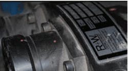
High-torque drive applications typically involve larger load inertias and slower ramp times for acceleration and deceleration than those of standard applications. Therefore, abrupt and unintentional load stoppages are potentially more damaging to drive components than for lighter equipment designed for quicker movements.
What's more, motors, drive shafts, and gearboxes are typically sized for the dynamics of a machine under normal conditions, and not necessarily for accidents, which can take a load from full speed to zero in mere seconds.
Such instances of jamming, crashing, and emergency braking involve torque values many times greater than what the machine requires for startup and operation, and what the driveline components have been designed to handle.
For this reason, mechanical torque limiters have existed for many years, allowing for a safety breakaway at a torque value above the level required for standard operation, but below the value that would overload and damage equipment.
However, this begs the question: How do engineers determine the torque that meets these contradictory requirements?
Retrofit in the field
In many cases, torque overload problems are only discovered and addressed after machine installation, so torque limiters are often sized for retrofit in the field — which complicates selection and implementation. The best way to determine disengagement torque value is to calculate the maximum torque rating of either the weakest component or the one that previously failed from overload. However, depending on when and where the machine was built, this information is not always available. Therefore, many torque limiters are field adjustable; in addition, a satisfactory disengagement torque value typically lies within a fairly wide range.
Other methods of determining the initial sizing of torque limiters also exist when certain details are missing. For example, a speed-based horsepower-to-torque calculation can be made, multiplied by any applicable gear reduction ratio, and then multiplied by an acceleration factor of three.
This method yields a disengagement torque value greater than the acceleration torque of most industrial equipment, but not high enough to damage driveline components. Caution: Make sure to allow ample headroom for upward adjustment of the disengagement torque when sizing this way.
Safety-element torque limiters
Safety-element type torque limiters also offer a reliable means of arriving at the appropriate disengagement torque setting. In standard configurations, sets of three, six, or nine individually spring-loaded ball-detent plungers are used to clutch the load and disengage at overload.
Subsequent reengagement simply involves snapping plungers back into place with a mallet, pry bar, or screw tool, taking only minutes to perform. Individual plunger modules are adjustable and set according to a tangential force value. The modules, set to equal force values, are then evenly spaced around a mounting circle.
Torque is determined by multiplying the setting of the modules by the number of modules and the radius from the center of the shaft module's mounting diameter.
For example, with three modules, each set to 5,000 N, and mounted on a 1,000-mm diameter, the disengagement torque setting is 7,500 Nm:
3 × 5,000 N = 15,000 N
1,000 mm ÷ 2 = 500 mm
15,000 N on a 500 mm radius = 7,500 Nm
Changing the settings of individual modules allows for finer adjustment. In the case of gross miscalculation of disengagement torque, additional modules can be added, taking the torque limiter up to the next adjustment range. To this end, safety-element torque limiters are often delivered with all nine receptacles prepared, even when as few as three modules are initially installed.
While mechanical ball-detent torque limiters are often designed with a high degree of accuracy and sensitivity, selecting torque limiters for retrofit is not an impossible undertaking. With several varieties of mounting options and configurations available, safety-element torque limiters are a useful means of making sure machinery stays up and running, even when catastrophe strikes.
For more information, visit rw-america.com or call (888) 479-8728.
