Talkin' about Shaft: Basics of line shafts, jackshafts, and torque tubes
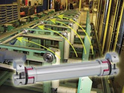
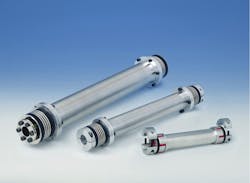
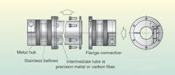
They're lightweight with straightness and lateral stiffness that boost stability at higher speeds. Line shafts, also known jackshafts and torque tubes, span long distances to connect other power transmission shafts. Conventional designs require an intermediate bearing or a pillow block in the drive system for supporting purposes. In contrast, newer high-precision line shafts run smoothly and can operate without intermediate support — even to 6 m. Line-shaft structure is similar to that of precision couplings: The main components are hubs in various designs, and a metal bellows or an elastomer insert, plus an intermediate tube made of aluminum, steel, or carbon fiber.
First objective in line-shaft use: Minimize vibration
Let's review some physics here: If a body is deflected in one direction by an acting force (for example, by an imbalance force at a high rotational speed) the body will recoil and deflect in the opposite direction as soon as the force is removed. Continued after the jump ...
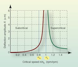
This deflection's amplitude leads to flexural body vibration, which settles at a rate that depends on the body's specific spring constant — so settling time is different in each case. However, if the excitation frequency periodically corresponds with the natural resonant frequency, the vibration will build instead — or more technically, will continuously increase in amplitude. The speed that causes vibrations to build is sometimes called the critical speed. Worst-case scenario, increasing amplitude can cause the line shaft to break — and any system not resistant to vibration has such resonant frequencies.
In the case of line shafts, vibration-inducing forces can be generated in two different ways: by an imbalance in attached rotating masses, or by the fact that the intermediate tube itself is never absolutely straight, but always deviates from its centerline slightly. Total line shaft deflection, and thus the difference between the ideal and actual axis of rotation, can be calculated by adding these two deviations — more on this in a moment.
Another consideration is maximum operating speed. Maximum operating speed, defined by manufacturers, is normally about 60 to 80% of critical speed, though line shafts manufactured with very precise concentricity can operate quite safely at 80% of critical speed. Keeping below this guarantees that the line shaft is never operated within the critical speed range.
Running the gantlet
What if a design requires a speed higher than a certain line shaft's critical speed? Is that particular line shaft unusable in that application, even if it's appropriate in all other ways? In special cases, and after consulting the coupling manufacturer, line shafts can be operated at more than 20% above the critical speed, in what's called the super-critical range, provided that the entire application is highly dynamic.
In these situations, operating speed should be reached within one or two seconds at most. This short period gives no prolonged opportunity for excitation, and thus prevents axial amplitude growth.
The line shaft should also be very rigid. Operating a line shaft at critical speed puts an additional load on the intermediate tube and the entire line shaft, so this additional load should be taken into account during design.
Design and selection
Determining critical speed is an important calculation when selecting line shafts. At this rotational speed, vibration continuously builds because of two things: deflection from specific weight fE and deflection resulting from the fact that the tube is never absolutely straight — fR. To calculate total line shaft deflection fm, these two factors are added:
fm = fE + fR
Total deflection prevents the line shaft from rotating exactly on the ideal axis of rotation. This creates an additional centrifugal force that stresses the line shaft.
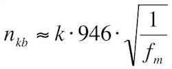
An explicit calculation of critical speed that takes all influencing factors into account, is very sophisticated and complicated. So here, we give a very rough formula. The critical speed (nkb) for axes and shafts, taking the bearing into account, is calculated:
Where k = Bearing correction factor
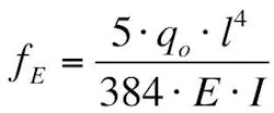
Rotationally borne axes or shafts that are not clamped (which are most common) have a non-adjusting correction factor of k = 1; in comparison, fixed axes clamped at the ends or with rotating discs, wheels, and similar components on them are calculated with a correction factor of k = 1.3. For line shafts, the correction factor k = 1 is normally used. As explained, the maximum deflection of the shaft is determined by two criteria. The second criterion, tube straightness, can be actively improved by using special ball bearing sets and test devices. But deflection caused by the specific weight is a constant value that cannot be changed: It depends on wall thickness, line shaft length, the elasticity modulus of the intermediate tube material, and other factors:
qo = Intermediate tube's specific weight
E = Material's elasticity modulus
I = Area moment of inertia with cylindrical hollow bodies
l = Intermediate tube length, mm
As with the last formula, this only yields rough results. For precise data on critical speed and the corresponding total deflection in a specific application, coupling manufacturers often have special calculation programs to simulate operations.
The role of rigidity
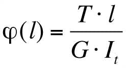
Torsional rigidity is also a factor. The torsion angle of the tube when subjected to a certain torque load is important in machine tools or position drives, for example, where load must be positioned precisely. The general formula for torsion angle is:
Where G and It are constant.
Ø= Torsion angle
T = Torque
G = Shear modulus
It = Torsional moment of inertia
The integral is solved by replacing the variable x with the length of the tube l:
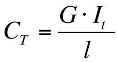
The formula for calculating the torsion angle can be simplified, because the torsional rigidity conforms to a natural law: The torsional rigidity is the result of the quotient of the shear modulus multiplied by the torsional moment of inertia and the length of the intermediate tube:
Where CT = Torsional rigidity, Nm/rad
To obtain a line shaft's work out, total torsion angle must be calculated. This includes the torsion angle of the intermediate tube, as well as the torsion angles of individual elastomer inserts or metal bellows uses.
Torsionally rigid line shafts
The structure of torsionally rigid line shafts is similar to that of metal bellows couplings: They have high torsional rigidity, low restoring forces, and compensate for misalignment. Hubs and stainless steel metal bellows are used to span the distance between the driving and the driven shaft. In between is a precision aluminum, steel, or (for shafts that run at a very high rotational speed) carbon fiber tubing. Torsionally rigid line shafts handle torques ranging form 10 to 4,000 Nm and bore diameters ranging from 5 to 100 mm. Line shafts are made of aluminum, steel, or stainless steel. They can be anodized, oxidized, or chromium or nickel plated.
Gimbals
The special internal gimbals of these line shafts make it possible to span a distance between the driving and the driven shaft of up to 6 m without an intermediate bearing. These gimbals hold the weight of the intermediate tube, so there is no additional radial load placed on the bellows. A fixed clearance prevents the maximum admissible compensation angle from being exceeded. Gimbals also provide additional safety, so if the worst occurs, and the axis is operated at critical speed, and vibration of the shaft builds, they prevent the intermediate tube from coming loose in an uncontrolled manner. The line shaft, obstructed, would come to rest without damaging surrounding components.
Disassembling units
There are two types of torsionally rigid line shafts. The first type, disassembling units, come apart and are suitable for being mounted wherever there is limited space and the line shaft cannot be inserted in its full length — for example, if a protective cover is located above the shaft. Therefore, the line shaft is separated into three parts before mounting: Flage screws are loosened, the two coupling ends are clamped onto the driving and driven shafts, and the intermediate tube is then reinserted.
Solid units
The second type is mounted without disassembly. They allow a more common lateral installation with split hubs that connect the driving and driven ends. Here, each hub consists of two components. The main body is brought over the two shafts to be connected, and then the split-hub pieces clamp back onto the line shaft.
Vibration-damping line shafts
Units with elastomer inserts called vibration-damping line shafts can compensate for vibration and torque impacts, transmit torques of more than 2,200 Nm, and can be mounted to shafts with bore diameters to 80 mm.
Their hubs are split and can be completely removed in a lateral direction. After the line shaft has been installed, it is fixed by the other half of the hub. The mounting process is quick and easy, as with split-hub metal bellows couplings. Too, shaft distances of more than 4 m can be spanned without an intermediate bearing.
Adjustable units
Machine and plant layouts are becoming increasingly diverse. Adjustable-length line shafts are one option rising to the challenge here, able to compensate for changes in length of more than 1,500 mm. They transmit torques to 800 Nm. To change total length, two screws on the clamping hub on the intermediate tube are loosened; then the line shaft can telescope to the required length. The frictional connection required to transmit torque is re-established by retightening the two screws; mounting and dismounting takes only a few minutes.
Thank you to Tobias Wolf, R+W America, Bensenville, Ill. for contributing technical informaiton to this article. For more information on flexures and how misalignment, shaft finish, clamping force, and vibration affect line shaft selection, call (888) 479-8728 or visit rw-america.com.
