Understanding the basics of amorphous-iron motors
Most engineers think amorphous iron is an exotic material that is hard to come by. But the interest level in this metal is rising because its magnetic properties can promote energy efficiency in electrical machinery and power distribution equipment. So it is timely to review the properties of amorphous iron that make it useful as a component in electrical equipment.
Despite what many engineers think, amorphous iron is actually made in large quantities. Two firms now supply the entire world’s amorphous iron: Metglas in Conway, S.C., and Tokyo (a division of Hitachi Metals), and Advanced Technology & Materials Co. Ltd. (AT&M) in China. About 100,000 tons of amorphous iron is produced annually, with Hitachi Metals supplying the vast majority.
Typical amorphous iron is an alloy of iron with boron and silicon. Amorphous iron comes from these suppliers in the form of a thin (25-microns thick) ribbon or foil. This form factor arises directly from the process used to manufacture the iron: Molten iron drips onto a wheel comprised of pure molybdenum. The molybdenum wheel is kept at a controlled temperature so iron hitting the wheel quenches quickly. The molten iron temperature drops at a rate of about 1 million°C/sec. This extra-fast quench freezes the iron molecules before they have a chance to form crystals, resulting in an amorphous structure that is much less orderly than that of crystalline iron.
This file type includes high resolution graphics and schematics when applicable.
The amorphous iron harvested from the molybdenum wheel is necessarily thin. At thicknesses exceeding about 25 microns, the temperature doesn’t drop as quickly for the internal iron molecules. These internal molecules would have time to form crystals so the resulting metal would lose its uniform amorphous quality.
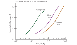
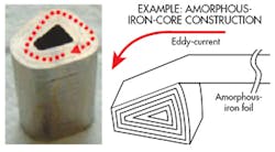
The disorderly structure of the amorphous iron lets it respond to changes in magnetic fields more readily than is the case for ordinary crystalline iron. The magnetic field change also causes eddy currents in the iron that are an additional source of loss, and the superthin nature of the amorphous iron limits these as well. Thus amorphous iron exhibits much less power loss, typically measured in units of Watts-per-pound or Watts-per-kilogram, for a given magnetic field strength than does crystalline iron.
This file type includes high resolution graphics and schematics when applicable.
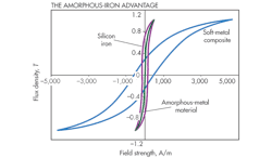
The advantage amorphous iron provides also becomes evident in magnetization curves (also called BH curves or hysteresis curves). When these curves are plotted for ordinary iron under the influence of alternating (ac) fields, a hysteresis effect is apparent because the iron stores some amount of magnetic energy. Said another way, there is a measureable difference between the magnetizing field H and the magnetic field B of the iron as the H field alternates polarity. But amorphous iron has a hysteresis that is nearly nonexistent at frequencies normally used in ac power equipment.
That said, amorphous alloys saturate at a lower flux density than do ordinary irons. Because its flux density is lower, electrical applications must use more amorphous material than would be necessary with crystalline iron to handle a given level of magnetic flux. Also, it can be difficult to work with amorphous iron without changing its magnetic properties. So, for example, there may be problems stamping out laminations of the material as is normally done to form components for squirrel-cage rotors in induction motors.
Amorphous-core losses and sizing
These issues as well as others have generally kept amorphous iron out of motor applications until relatively recently. The main use for the material has been in distribution transformers. That is because a transformer’s no-load loss primarily originates in the transformer core. Amorphous-core losses can be on the order of 75% lower than those of traditional crystalline iron. But under appreciable loads, the lower saturation magnetization of amorphous iron tends to lower efficiency. Transformer manufacturers typically use more copper and core material to compensate. So high-efficiency amorphous-core transformers tend to be larger than ordinary models with the same ratings. And because they use more expensive amorphous iron and additional copper windings, they cost more than traditional transformers as well.
Amorphous-core transformers have primarily been produced and installed in India and China. There is no technical reason why amorphous iron could not be used in U. S. transformers. The transformers have found a home in Asia primarily because energy costs there are higher than in North America so efficiency measures have a faster payback. Also, North America has a large installed electrical infrastructure with a lot of sunk costs. All in all, the most likely role for amorphous transformers in the U. S. will be as replacement units where the economic payback justifies the extra cost.
This file type includes high resolution graphics and schematics when applicable.
Motor topology
There have been a number of motors constructed with amorphous iron through the years. Until recently, nearly all have been academic studies. It looks likely that amorphous-iron motors will have a commercial niche. Their low switching losses and lower flux density makes them candidates for applications at higher motor frequencies, perhaps at magnetic field frequencies of 350 Hz or higher. Also, amorphous iron is well suited to brushless-motor topologies because their rotors are basically comprised of magnetic material.
Several application areas come to mind where these qualities apply. One in particular is that of powering scroll compressors. These compressors are isentropically more efficient than piston compressors. Many of these units that serve as air compressors run at 2,400 rpm and at synchronous frequencies where amorphous-iron motors can excel. Similarly, some centrifugal pumping applications run at 3,600 rpm simply because this operating point corresponds to the top speed of the two-pole/60-Hz motors that power them. But the optimal efficiency for such pumps is at 7,500 rpm. This operating point is well within the realm of amorphous-motor designs.
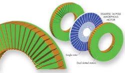
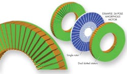
But the amorphous motors that power such applications will probably have topologies unlike those of conventional brushless motors due to the realities of working with amorphous-iron foils that are only 25-microns thick. The magnetic teeth, for example, will likely be smaller than those of conventional silicon-iron motors. The practice of using small amorphous teeth lends itself to the construction of motors with a high pole count. One commercial design uses two stators each containing 54 amorphous-iron poles. The full-speed frequency of this device is 1 kHz.
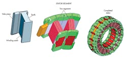
Another design now in production uses what is called a segmented stator. Its structure is devised to avoid difficulties associated with efficiently assembling a stator with amorphous-iron teeth. A yoke made from either a soft magnetic material or amorphous iron holds individual iron teeth. The yoke is made of individual pieces that are assembled to the teeth after copper windings are formed around each of the teeth. Each yoke piece has a tongue-and-groove to let multiple yoke pieces connect to the teeth. This lets the individual stator tooth pieces be wound with copper wire while sitting flat. Once windings are completed on the teeth, the yoke pieces can be connected together to form a complete stator.
Andrew Hirzel is an engineer at Radam LLC, Grand Rapids, Mich.
This file type includes high resolution graphics and schematics when applicable.
