Encoders for feedaxes with direct drives
Direct drives place rigorous demands on position-signal quality. Optimum measuring signals increase the quality of the machined workpiece surface, reduce vibration in the machine frame, stop excessive noise exposure from velocity-dependent motor sounds, and prevent additional heat generation in the motor. Direct-drive efficiency is greatly influenced by the selection of the position encoder. Encoders with optical scanning methods provide benefits in the accuracy, speed stability, and thermal behavior of a direct drive.
Construction of direct drives
The decisive advantage of direct drive technology is the stiff coupling of the drive to the feed component without any other mechanical transfer elements. This allows significantly higher kV factors in the control loop than a conventional drive.
On direct drives, there is no additional encoder for measuring the speed. Both the position and the speed are measured by the position encoder: linear encoders for linear motors, angle encoders for rotating axes. Since there is no mechanical transmission between the speed encoder and the feed unit, the position encoder must have a correspondingly high resolution for exact velocity control at slow traversing speeds.
Higher kV factors also increase the influence of the position encoders’ signal quality on positioning behavior. Direct drives therefore require position encoders with small signal periods and high signal quality.
Signal quality of position encoders
Modern encoders feature an incremental (which means counting) or absolute method of position measurement. The path information is transformed in the encoder into two sinusoidal signals with 90° phase shift. Both methods require that the sinusoidal scanning signals be interpolated in order to attain a sufficiently high resolution. Incomplete scanning, contamination of the measuring standard, and insufficient signal conditioning can lead to the signals deviating from the ideal sinusoidal shape.
Interpolation generates shortwave errors whose periodic cycle is within one signal period of the encoder’s output signals. These errors are termed “position errors within one signal period,” or also “interpolation errors.” On highquality encoders they are typically 1 to 2% of the signal period.
Interpolation error not only affects the position accuracy, but also influences the speed stability of the drive. The speed controller calculates the nominal currents used to brake or accelerate the drive depending on the error curve. At low feed rates, the feed drive lags the interpolation error. Since direct drives have a greater control bandwidth due to the kV factor, they can lag the interpolation error over a larger speed range. This can lead to wave-like errors on the workpiece surface during cutting processes. The wavelength and amplitude depend on the speeds of the machine axes involved in the feed rate.
Generation of heat and noise
If the frequency of the interpolation error increases, the feed drive can no longer follow the error curve. However, the current components generated by the interpolation error increase motor noise and heat.
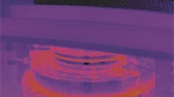
A comparison of the effects of an optical angle encoder and a magnetic modular rotary encoder on a rotary table with direct drive emphasize the meaning of high-quality position signals. The angle encoder with 16,384 lines generates only barely noticeable disturbances in the motor current, and the motor operates normally and develops little heat. Because of the magnetic scanning principle, the rotary encoder has notably fewer signal periods. Significant disturbances occur in the motor current at the same controller settings, causing an increase in motor noise and heat.
Continue on page 2
Digital filters are often used with direct drives to smooth the position signals. However, the loss of phaseassociation by filtering in the speedcontrol loop must be kept to a minimum, otherwise the dynamic accuracy decreases. Position encoders with optimum signal quality help to reduce the use of filters, meaning that the control bandwidth is maintained.
Position encoders for direct drives
Position encoders that generate a high-quality position signal with a small signal period are essential for optimal operation of direct drives. Encoders that use photoelectric scanning are ideally suited for this task, since very fine graduations can be scanned by this method.
Encoders with photoelectric scanning incorporate measuring standards of periodic structures known as graduations. These fine graduations are manufactured in a photolithographic procedure and are characterized by high edge definition and homogeneity. Typical graduation periods are from 40 μm to under 1 μm.
A wide range of photoelectric linear and angle encoders are available for various applications. For example, sealed linear encoders on machine tools provide the measuring standard with optimum protection against chips, dust, and splash fluids. Exposed linear encoders are ideal for applications with a low risk of contamination, such as in the semiconductor industry. Depending on the model, either very rapid traverse speeds or the highest positioning accuracy are possible.
Incremental encoders are increasingly being complemented by encoders that measure the position absolutely, since the position is available immediately after switch-on of these encoders.
Absolute measuring procedures eliminate the need for reference runs. Absolute encoders are especially advantageous on direct drives. Both the current position and the commutation offset are immediately known as soon as the encoder is switched on. The motor can be powered-up at once, and is supported in the control loop. Critical operating states, such as switching on a vertical axis with direct drive or retraction after an emergency stop, are controlled safely.
