To maintain its edge in a highly competitive industry, J.I. Case Backhoe/Loader Div., Burlington, Iowa, strives to continually improve product quality while reducing costs through streamlined manufacturing operations and state-of-the-art production technologies. An advanced method of welding a key component in Case backhoes provides one example of the company’s manufacturing improvements.
The component, called a swing frame, couples a backhoe’s bucket arm with the tractor. The 600-lb swing frame’s structural integrity is ensured by accurately welding its parts with the help of a precision welding positioner. Chris Shelb, application engineer at Davenport, Iowa based Genesis Systems Inc., explains that the positioner they developed for Case is integrated with a precision robotic welding arm, Figure 1. To fully utilize the robotic arm’s capability, servodriven gearing must operate bidirectionally with virtually no backlash.
To achieve this level of precision, Genesis turned to Cone Drive Operations, a Textron subsidiary in Traverse City, Mich., and became an early user of their split worm gear, called AccuDrive, which eliminates backlash without the usual engineering tradeoffs.
Previous attempts to eliminate backlash were costly, cumbersome, and ineffective. Machine builders typically crammed the gears together to minimize looseness, which requires a lot of hand fitting and alignment modifications. With this approach, results were inconsistent from one unit to the next, some gears failed, and backlash could only be reduced to 0.002 in. — not eliminated. Other, more sophisticated approaches were considered, but also had drawbacks. At Genesis, for example, mechanical designer Mike McCreary considered installing an additional idler pinion in the gearbox to force the driven gear teeth against the mating pinion gear teeth. “In some cases, especially singledirection drives, this might be an acceptable solution to backlash,” he explains. “However, in a bidirectional system, the extra design work would be costly and involve a great deal of mechanical monitoring and adjustments by the customer.” With the zero-backlash worm gearing, McCreary solved the backlash problem and avoided the need for customers to make adjustments.
Gear design concept
To understand how the new worm gear eliminates backlash, it’s necessary to consider the sources of backlash. In a worm gear speed reducer, backlash typically shows up in two forms: as gear set backlash and as worm bearing end play.
In a conventional worm gear set, some of the backlash is intentional and some is not. By design, the intentional portion provides space for an oil film between meshing teeth and sufficient running clearance to accommodate rotational error in both the gear set and supporting bearings. Unintentional backlash comes from machining errors — tooth spacing error, pitch line runout, and tooth profile error — plus wear.
Some bearing end play is considered necessary in continuous-duty worm gear applications — 0.001 to 0.006 in. play is generally shimmed into reducers during assembly to permit thermal expansion. Without this end play, heat buildup would cause binding and seizing in a hard-working worm reducer.
The new worm gear eliminates both sources of backlash with a split-worm design, Figure 2. A preloaded conical disc presses half of the worm threads against the gear teeth, eliminating gear set backlash in both directions of rotation. The loaded worm gear not only compensates for minute machining and rotational errors, it also adjusts automatically for both wear and thermal expansion.
Continue on Page 2
Welding positioner basics
At Case, the servo-driven zero-backlash worm gear units provide high repeatability over time, so operators of the Genesis welding positioners have to “teach” the robot complex welding sequences just once. Some sequences involve up to 45 min of automated operation. The frame can be rotated on two axes to allow the robotic welding arm to access an infinite number of indexed positions in various planes.
The 600-lb backhoe swing frame is mounted on a rotatable platter table, which is in turn mounted on a large Lshaped arm that rotates about a horizontal axis, Figure 1. One 600:1 worm gear speed reducer with 18,000 lb-in. torque capacity turns the platter table to which the swing arm is mounted, Figure 3, and another 600:1 unit, rated at 24,000 lb-in. of torque, rotates the arm. By rotating on two axes, the positioner keeps all frame positions within the robot’s work envelop or reach.
The welding positioner has operated daily at Case since 1991. According to Chris Shelb at Genesis, “That positioner handles 2,000 lb located 1 ft off the face plate with no rotational error. Our customer doesn’t run it at top speed, but it’ll do 360 deg on its major axis in 8 sec, and 10 rpm on its minor axis. That’s fast. All that with zero backlash after 2½ years running.” To confirm their satisfaction with the precision positioner, Case recently decided to order three more.
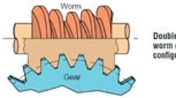
Worm gear combines high capacity and precisionThe AccuDrive worm gear uses a double-enveloping worm gear design to obtain high torque capacity. Double enveloping means that the worm and gear wrap around each other. This increases load capacity by providing more tooth area in contact and more teeth in mesh than other worm gear designs. Three levels of precision are available: zero backlash, low backlash (0.000 to 0.002 in.), and precision (0.000 to 0.004 in.). The precision reducer also comes with an adjustable center distance to provide 0.000 to 0.003-in. backlash. |
Related Articles
Design by objective
Design by objective: PRECISION & ACCURACY
